


12
Upgrading and Servicing Guide
Installing a Memory Module
Upgrade the memory in your PC with memory of the
same type and speed as the memory originally
installed in your PC.
CAUTION: When handling a memory
module, be careful not to touch any of
the contacts. Doing so may damage the
module.
1
Open both latches of the memory module socket.
See “Removing a Memory Module” on page 11.
•
If you are
replacing
a memory module, put the
new memory module in the same memory slot
from which the old memory was removed.
Or
•
If you are
adding
a memory module, install the
new module into the socket nearest the
preinstalled module, and install additional
modules in the next available sockets.
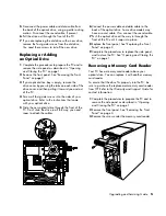
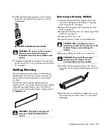
2
Hold the new memory module by its edges only as
you remove it from the antistatic packaging. Avoid
touching the memory chips or the gold contacts on
the module.
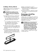
3
The memory module can be installed in only one
way. Match the notch on the module with the tab
on the memory socket. Push the module carefully
and firmly into the slot, ensuring that the latches on
both ends snap into place.
4
Replace any cabling that was removed.
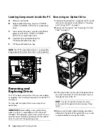
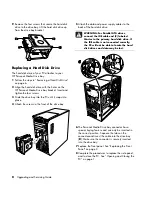
5
Complete the procedures to replacing a hard disk
drive and close the PC. See “Replacing a Hard
Disk Drive” on page 8.
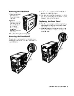
6
Complete the procedures to replace the side panel
and close the PC. See “Opening and Closing the
PC” on page 1.
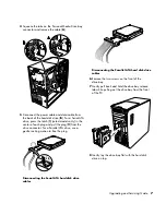
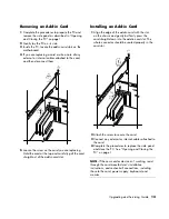
Removing or Installing
an Add-in Card
An add-in card is a circuit board, such as a PCI or an
AGP card, that fits into a PC add-in card slot. Your PC
contains several add-in card slots that can be used to
add components to your PC. The PC component
configurations vary by model.
WARNING: Do not overload the system
by installing add-in cards that draw
excessive current. The system is designed
to provide 2 amps (average) of +5 V
power for each board/card in the PC.
The total +5 V
current draw in a fully
loaded system (one with all add-in card
slots filled) must not exceed the total
number of slots multiplied by 2 amps.
A Phillips screwdriver is needed to remove, replace,
or add an add-in card.
Summary of Contents for s7600n - Pavilion Media Center
Page 1: ...Upgrading and Servicing Guide ...
Page 4: ...iv Upgrading and Servicing Guide ...
Page 19: ...Upgrading and Servicing Guide 15 ...
Page 20: ......


