
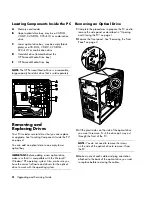

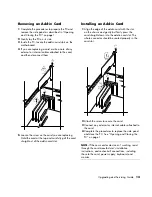


Removing an Add-in Card
1
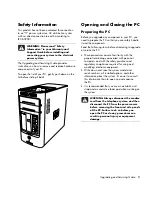
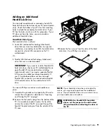
Complete the procedures to prepare the PC and
remove the side panel as described in “Opening
and Closing the PC” on page 1.
2
Gently lay the PC on its side.
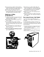
3
Inside the PC, locate the add-in card slots on the
motherboard.
4
If you are replacing a card, make a note of any
external or internal cables attached to the card,
and then disconnect them.
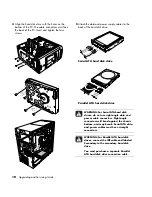
5
Loosen the screw on the card you are replacing.
Hold the card at the top and carefully pull the card
straight out of the add-in card slot.
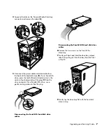
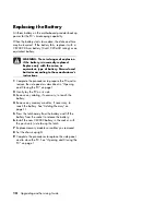
Installing an Add-in Card
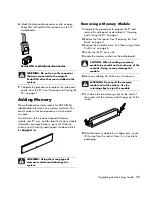
1
Align the edge of the add-in card with the slot
on the chassis and gently but firmly press the
card straight down into the add-in card slot. The
whole connector should be seated properly in the
card slot.
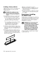
2
Attach the screw to secure the card.
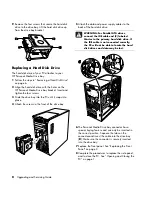
3
Connect any external or internal cables attached to
the card.
4
Complete the procedures to replace the side panel
and close the PC. See “Opening and Closing the
PC” on page 1.
NOTE:
If the new card or device isn’t working, read
through the card manufacturer’s installation
instructions, and recheck all connections, including
those to the card, power supply, keyboard, and
monitor.
Upgrading and Servicing Guide
13
Summary of Contents for s7600n - Pavilion Media Center
Page 1: ...Upgrading and Servicing Guide ...
Page 4: ...iv Upgrading and Servicing Guide ...
Page 19: ...Upgrading and Servicing Guide 15 ...
Page 20: ......