background image

Before Opening the PC 

To avoid injury and equipment damage, always 
follow this procedure in this order before opening 
the PC: 


Remove any diskette or optical disc (CD or DVD) 
from the PC. 

Click the 

Start

 button on the taskbar. Click 

Turn 

Off Computer

 and then click 

Turn Off

 again. 

Disconnect the modem/telephone cable, if present. 


WARNING: To reduce the risk of personal 
injury from electrical shock or hot 
surfaces, disconnect the power cord from 
the wall outlet, and allow the internal 
system components to cool before 
touching. 


Disconnect the power cord from the electrical outlet 
and then from the PC. 

Disconnect all other attached cables (such as the 
keyboard, mouse, and monitor). 

Disconnect all external devices. 


CAUTION: Static electricity can damage the 
electronic components of the PC or 
optional equipment. Ensure that you are 
discharged of static electricity by briefly 
touching a grounded metal object. 


After Closing the PC 

To avoid injury and equipment damage, always 
follow this procedure in this order after closing the PC: 

Reconnect the power cord. 


WARNING: To reduce the risk of electrical 
shock, fire, or damage to the equipment, 
do not plug telecommunications or 
telephone connectors into the network 
interface card (NIC) (labeled as an 
Ethernet connector). 


Reconnect the modem/telephone cable and all 
other attached cables (such as the keyboard, 
mouse, and monitor). 

Reconnect external devices. 

Turn on the PC and all peripherals such as the 
monitor. 

If you installed an add-in card, install any software 
drivers supplied by the card manufacturer. 


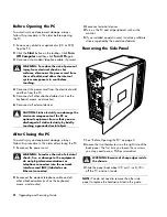
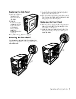
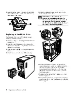
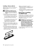
Removing the Side Panel 


See “Before Opening the PC” on page 2. 

Loosen the two thumbscrews on the right side of the 
back panel. The first time you loosen these screws, 
you may need to use a Phillips screwdriver. 


WARNING: Beware of sharp edges inside 
the chassis. 


Slide the panel back about 2.5 cm (1 inch), lift it 
off the PC, and set it aside. 


NOTE:

 You do not need to remove the other side 

panel to replace the hardware listed in this guide. 


2

    Upgrading and Servicing Guide 

Summary of Contents for s7600n - Pavilion Media Center

Page 1: ...Upgrading and Servicing Guide ...

Page 2: ... by copyright No part of this document may be photocopied reproduced or translated to another language without the prior written consent of HP Hewlett Packard Company P O Box 4010 Cupertino CA 95015 4010 USA Copyright 2000 2006 Hewlett Packard Development Company L P May be licensed in the United States by one or both of U S Patents Nos 4 930 158 and 4 930 160 until August 28 2008 Microsoft and Wi...

Page 3: ...g and Replacing Drives 4 Removing an Optical Drive 4 Replacing or Adding an Optical Drive 5 Removing a Memory Card Reader 5 Installing a Memory Card Reader 6 Removing a Hard Disk Drive 6 Replacing a Hard Disk Drive 8 Adding an Additional Hard Disk Drive 9 Adding Memory 11 Removing a Memory Module 11 Installing a Memory Module 12 Removing or Installing an Add in Card 12 Removing an Add in Card 13 I...

Page 4: ...iv Upgrading and Servicing Guide ...

Page 5: ...d the following items before attempting to upgrade or service the PC These procedures assume familiarity with the general terminology associated with personal computers and with the safety practices and regulatory compliance required for using and modifying electronic equipment Write down and save the system model and serial numbers all installed options and other information about the system It s...

Page 6: ...After Closing the PC To avoid injury and equipment damage always follow this procedure in this order after closing the PC 1 Reconnect the power cord WARNING To reduce the risk of electrical shock fire or damage to the equipment do not plug telecommunications or telephone connectors into the network interface card NIC labeled as an Ethernet connector 2 Reconnect the modem telephone cable and all ot...

Page 7: ... a memory card reader or a hard disk drive 1 Locate the three small tabs attached to the front panel on the side of the chassis 2 Press each tab away from the center of the chassis Press the top the middle and the bottom tab and then gently remove the front panel Replacing the Front Panel 1 Place the chassis upright and then align the three tabs on the right side of the front panel with the correc...

Page 8: ...RTANT Before adding a new optical drive make sure that it is compatible with the Microsoft Windows XP operating system Also make sure you have the correct software and drivers for the optical drive to work with the operating system Removing an Optical Drive 1 Complete the procedures to prepare the PC and to remove the side panel as described in Opening and Closing the PC on page 1 2 Remove the fro...

Page 9: ...h the front of the PC Don t slide the drive in all the way you need room to attach the cables 6 Connect the power cable and data cable to the back of the optical drive Some drive models may have a sound cable If so connect the sound cable 7 Push the optical drive all the way in through the front of the PC until it snaps into place 8 Replace the front panel See Replacing the Front Panel on page 3 9...

Page 10: ... is preloaded with the system recovery partition of your PC If you remove this hard disk drive store it in an antistatic bag that is properly sealed CAUTION Back up your personal files on the hard disk drive to an external storage device such as a CD before removing the hard disk drive Failure to do so will result in data loss After replacing the hard disk drive you need to run System Recovery usi...

Page 11: ...enter of each plug and pull the plug 2 from the drive connector For a Parallel ATA drive use a gentle rocking motion to free the plug Disconnecting the Serial ATA hard disk drive cables Disconnecting the Parallel ATA hard disk drive cables 6 Remove the two screws on the front of the drive bay 7 Gently pull back and hold the drive bay release tab while pulling out the drive bay from the front of th...

Page 12: ...ive bay 5 Attach the data and power supply cables to the back of the hard disk drive WARNING For Parallel ATA drives connect the IDE cable end C labeled Master to the primary hard disk drive If the IDE cable is not connected correctly the PC will not be able to locate the hard disk drives and data may be lost 6 The Personal Media Drive bay connector has a special keying feature and can only be ins...

Page 13: ...nnector before installing select models only You need a separate Parallel ATA connection cable purchased separately If your PC motherboard does not have an open Parallel ATA connector you cannot add a Parallel ATA hard disk drive but can add a Serial ATA drive You need a Phillips screwdriver and needle nose pliers 1 Complete the procedures to prepare the PC and to remove the side panel as describe...

Page 14: ...rd disk drive WARNING For Serial ATA hard disk drives do not use right angle data and power cable connectors Right angle connectors will bend against the chassis bottom and may break Serial ATA data and power cables must have straight connectors WARNING For Parallel ATA hard disk drives connect the IDE cable end labeled Secondary to the secondary hard disk drive You must purchase a separate Parall...

Page 15: ...ink WARNING Using the wrong type of memory module could damage the system Removing a Memory Module 1 Complete the procedures to prepare the PC and remove the side panel as described in Opening and Closing the PC on page 1 2 Remove the front panel See Removing the Front Panel on page 3 3 Remove the hard disk drive See Removing a Hard Disk Drive on page 6 4 Gently lay the PC on its side 5 Locate the...

Page 16: ... on the module with the tab on the memory socket Push the module carefully and firmly into the slot ensuring that the latches on both ends snap into place 4 Replace any cabling that was removed 5 Complete the procedures to replacing a hard disk drive and close the PC See Replacing a Hard Disk Drive on page 8 6 Complete the procedures to replace the side panel and close the PC See Opening and Closi...

Page 17: ...add in card slot Installing an Add in Card 1 Align the edge of the add in card with the slot on the chassis and gently but firmly press the card straight down into the add in card slot The whole connector should be seated properly in the card slot 2 Attach the screw to secure the card 3 Connect any external or internal cables attached to the card 4 Complete the procedures to replace the side panel...

Page 18: ...lete the procedures to prepare the PC and to remove the side panel as described in Opening and Closing the PC on page 1 2 Gently lay the PC on its side 3 Remove any cabling if necessary to reach the battery 4 Remove any memory modules if necessary to reach the battery See Adding Memory on page 11 5 Press the latch away from the battery and lift the battery from the socket to release the battery 6 ...

Page 19: ...Upgrading and Servicing Guide 15 ...

Page 20: ......

Reviews: