


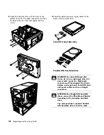


5
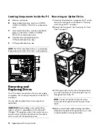
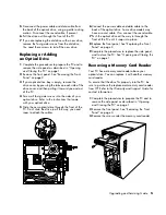
Disconnect the power cable and data cable from
the back of the optical drive, using a gentle rocking
motion. Disconnect the sound cable, if present.
6
Pull the drive out through the front of the PC.
7
If you are replacing the old drive with a new drive,
remove the four guide screws from the old drive.
You need these screws to install the new drive.
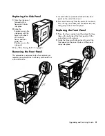
Replacing or Adding
an Optical Drive
1
Complete the procedures to prepare the PC and to
remove the side panel as described in “Opening
and Closing the PC” on page 1.
2
Remove the front panel. See “Removing the Front
Panel” on page 3.
3
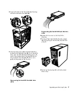
If your optical drive bay is empty, remove the
drive cover by pressing the tabs on each side of the
drive cover, and then pulling it toward you and out
of the PC.
4
Screw all four guide screws into the sides of your
optical drive. Refer to the instructions that came
with your optical drive.
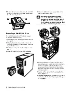
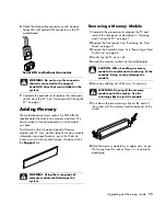
5
Slide the new optical drive through the front of the
PC. Don’t slide the drive in all the way; you need
room to attach the cables.
6
Connect the power cable and data cable to the
back of the optical drive. Some drive models may
have a sound cable. If so, connect the sound cable.
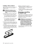
7
Push the optical drive all the way in through the
front of the PC until it snaps into place.
8
Replace the front panel. See “Replacing the Front
Panel” on page 3.
9
Complete the procedures to replace the side panel,
and to close the PC. See “Opening and Closing the
PC” on page 1.
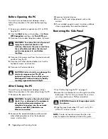
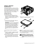
Removing a Memory Card Reader
Your PC has a memory card reader above your
optical drive. You can replace it with another memory
card reader.
To ensure that the drive fits properly into the PC, be
sure to purchase the replacement memory card reader
from HP. Refer to the
Warranty and Support Guide
for
contact information.
1
Complete the procedures to prepare the PC and to
remove the side panel as described in “Opening
and Closing the PC” on page 1.
2
Remove the front panel. See “Removing the Front
Panel” on page 3.
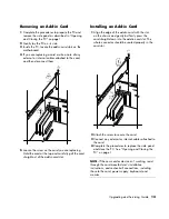
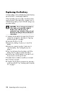
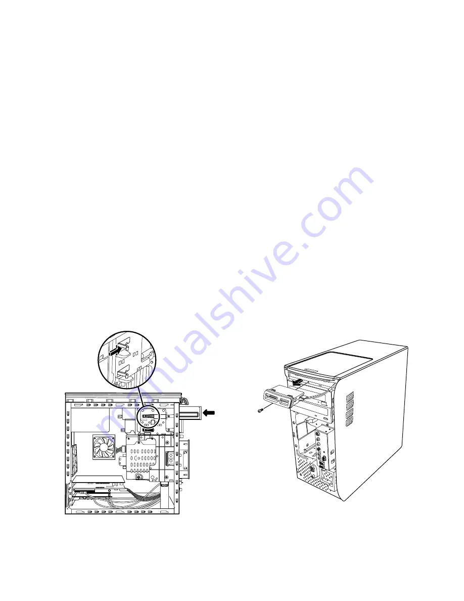
3
Remove the screw under the memory card reader.
Upgrading and Servicing Guide
5
Summary of Contents for s7600n - Pavilion Media Center
Page 1: ...Upgrading and Servicing Guide ...
Page 4: ...iv Upgrading and Servicing Guide ...
Page 19: ...Upgrading and Servicing Guide 15 ...
Page 20: ......


