background image

6

Check motor. 
It may be equipped

with an automatic resetting thermal 
protector and may restart unexpectedly 
(see specifications chart). Protector tripping
is an indication of motor overloading as a
result of operating the pump at too high a
pressure (over 100 PSI), too high of viscosity,
too high of specific gravity, excessively high
or low voltage, inadequate wiring, incorrect
motor connections, too small a motor 
(sized incorrectly, not enough HP), or a
defective motor or pump.

Do not handle pump with wet hands 
or when standing in water. Failure to 
follow the General Safety Information 
and all warnings could result in fatal 
electrical shock!

Assembly 

(If pump and motor are
pre-assembled, skip assembly.)

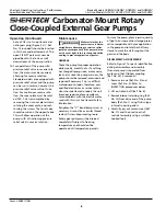
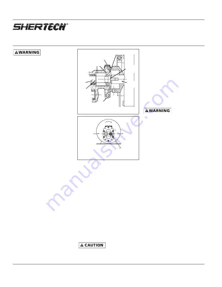
1. Refer to Figures 2 and 3.

2. Remove the hex head machine

screw from the ”V“ band clamp.

3. Slide the ”V“ band clamp away

from the mating face (do not
remove from the pump).

4. Match the pump mating face and

motor mounting hub, while mating
shafts and Oldham coupling (Ref.
No. 24, Figure 7). 

NOTE:

The small

end of coupling goes into pump.

Rotation: When looking at the motor
shaft end, proper motor pump rotation
is clockwise (CW). Flow is left to right
(See Figure 3). Reverse the flow by
rotating the pump 180˚. Standard mod-
els are equipped with pressure relief
valves. It is important that the relief
valve be on the discharge side of the
pump. 

NOTE:

Pump can be rotated 360°.

5. Slip the ”V“ band clamp over the

pump and motor halves (See Figure
2) and tighten the hex head clamp
screw to hold the assembly together.

6. Retighten the ”V“band clamp screw

as necessary. Use thread sealant if
screw keeps coming loose.

Installation 

IMPORTANT:

In any installations where

property damage and/or personal 
injury can occur when the pump is 
not operating due to power outages, 
discharge line freezing, or any other
reason, a back-up system(s) and/or
warning system(s) should be used.

In order to safely use this product, familiar-
ize yourself with this pump and also with
the liquid (chemical, etc.) that is going to
be pumped through the unit. This pump is
not suitable for many liquids.

1. Locate the pump as close to the 

liquid source as possible, making 
the suction line as short and direct
as possible.

Ambient
temperature around

motor should not exceed 104˚F (40˚C).

2. Open drip-proof motors are

designed to be used in clean, dry
locations with access to an adequate
supply of cooling air.

3. For outdoor installations, the motor

must be protected by a cover that
does not block air flow to and
around the motor.

4. The motor should be securely 

fastened to a rigid surface, 
preferably metallic. For rigidity, 
use largest bolts that will fit
through the base holes.

Do not use to
pump flammable or

explosive fluids such as gasoline, fuel oil,
kerosene, etc. Do not use in flammable
and/or explosive atmospheres. When 
pumping hazardous or dangerous materials,
use only in room or area designated for 
that purpose.

For your protection, always wear proper
clothing, eye protection, etc. in case of any
malfunction. For proper handling techniques
and cautions, contact your chemical supplier,
insurance company and local agencies (fire
dept., etc.). Failure to comply with this 
warning could result in personal injury
and/or property damage.

PIPING 

SUCTION

1. Avoid excessive lengths or number of

fittings and bends in the suction line.

2. Attach suction line to suction inlet.

3. It is recommended that same size

pipe as pump ports be used or, in
cases requiring lengthy piping, the
next larger size pipe be used.

4. If suction lift is greater than what is

indicated in the performance chart,
attach a foot valve below liquid
level at end of suction line to ensure
positive priming. Also note: If fluid
specific gravity is greater than 1.4 or
viscosity greater than 500 SSU, a
foot valve is also recommended.

5. If solid contaminates are suspected

in a liquid, place a filter in the 
suction line.

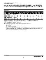
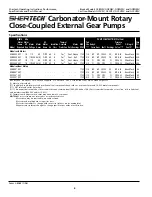
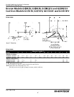
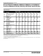
Bronze Models GCBN2V, GCBN3V, GCBN22V and GCBN33V

Cast Iron Models GCCV2V, GCCV3V, GCCV22V and GCCV33V

Shertech Operating Instructions, Performance, 
Specifications and Parts Manual

Form L-4083 (1/06)

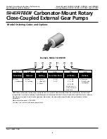
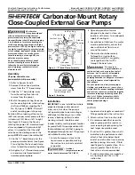
Carbonator-Mount Rotary

Close-Coupled External Gear Pumps

IN

ROTATION

Pressure relief valve 
(on discharge side)

OUT

Figure 3 - Rotation

Int. Ret. Ring

Oldham
Coupling

Motor
Shaft

Pump
Shaft

Ext. 
Ret.
Ring

Hex. Head
Clamp Screw

Seal Seat Assy.

Figure 2 - “V” Band Clamp Assembly

“V”Band Clamp

Summary of Contents for Shertech GCBN22V

Page 1: ...or use with oil based fluids Not to be used with water based fluids Pumps include steel spur gears with steel shafts and cast iron shaft support standard pressure relief valves that can be ported internally or externally and a Viton mechanical carbon ceramic faced seal with temperature range of 32 to 280 F Wet end parts are constructed from cast iron steel stainless steel 302 303 and or 18 8 carbo...

Page 2: ...HP 3 1 2 HP V Pressure Relief Valve Standard 1st 2nd 3rd 4th 5th 6th Mounting Material Sealing Gear Size Ports AC Motor Options NOTE Not all order code combinations configurations are standard models available from the manufacturer Custom model configurations may require ordering standard components and or optional parts that will need to be assembled by the customer Manufacturer reserves the righ...

Page 3: ... by 10 Don t use water with Cast Iron Pump performance when pump is new As pump wears the performance will decrease NPT inlet and outlet in inches Suction lift requires wetted gears and primed seal chamber Motor not provided NOTES Pumps with motors are HP rated to handle up to 500 SSU at 100 PSI and specific gravity of 1 0 Max PSI 100 Max Viscosity 500 SSU Max RPM 1725 Max Specific Gravity 1 1 at ...

Page 4: ...5 3 8 CI CRS CRS CI CRS SS Viton Mech 22 3 Models without Motors GCBN2V 48Y 1725 1 4 BZ BZ 303 SS CG BR SS Buna Mech 4 3 GCBN3V 48Y 1725 3 8 BZ BZ 303 SS CG BR SS Buna Mech 4 8 GCCV2V 48Y 1725 1 4 CI CRS CRS CI CRS SS Viton Mech 4 0 GCCV3V 48Y 1725 3 8 CI CRS CRS CI CRS SS Viton Mech 4 3 BZ Bronze BR Brass CG Carbon Graphite CI Cast Iron CRS Cold Rolled Steel ODP Open Drip Proof Motor not provided...

Page 5: ...3 4 11 16 35 8 21 2 GCBN33V GCCV33V 3 8 21 4 27 16 3 7 89 16 23 4 55 8 41 4 53 4 11 16 35 8 21 2 Models without Motors GCBN2V GCCV2V 1 4 129 32 3 69 16 35 8 21 2 GCBN3V GCCV3V 3 8 21 4 3 7 35 8 21 2 NPT inlet and outlet in inches This dimension may vary due to motor manufacturer s specifications NOTE Dimensions have a tolerance of or 1 8 Manufacturer reserves the right to change dimensions without...

Page 6: ... Locate the pump as close to the liquid source as possible making the suction line as short and direct as possible Ambient temperature around motor should not exceed 104 F 40 C 2 Open drip proof motors are designed to be used in clean dry locations with access to an adequate supply of cooling air 3 For outdoor installations the motor must be protected by a cover that does not block air flow to and...

Page 7: ...s and this tolerance must not be altered The liquids must therefore be free of all abrasives Sand silt wettable powders etc must be avoided NOTE Cast iron pumps are for oil based fluids only 3 When pumping a more viscous beyond 500 SSU liquid a slower speed a larger pipe size pump and possibly a larger motor should be selected NOTE See performance chart for Max Torque 4 Recheck motor rotation Prop...

Page 8: ... is a difficult motor pump to repair therefore only qualified electricians or service techni cians should attempt to repair this unit Improper repair and or assembly can cause problems with the electric motor used with this unit See General Safety Information Retighten the V band clamp screw as necessary Use Loctite or similar thread sealant if screw keeps coming loose Rotary gear pumps must be dr...

Page 9: ...d Do not run pump dry as permanent damage to the pump gears seal and bearings will result Suction pressure should never be greater than the discharge pressure Mechanical Seal Replacement Refer to Figures 6 7 for parts identification 1 Remove pump from motor if not already done 2 Remove snap ring Ref No 12 Pry out seal seat Ref No 11 Pull mechanical seal Ref No 10 off shaft See Assembly 3 through 5...

Page 10: ...t the pump head be replaced Note that seals and o rings used in each material type are interchangeable The Viton components from the cast iron models can be used in the bronze and the Buna in the bronze models can be used in the cast iron models Figure 7 Repair Parts Illustration Please provide following information Model number Serial number if any Part description and number as shown in parts li...

Page 11: ...A NA NA NA NA NA 1 14 External Bypass Relief Plug NA NA NA NA NA NA NA NA 1 15 Relief Valve Cap NA NA NA NA NA NA NA NA 1 16 Washer NA NA NA NA NA NA NA NA 1 17 Hex Nut NA NA NA NA NA NA NA NA 1 18 Set Screw 18 8 SS NA NA NA NA NA NA NA NA 1 19 O ring NA NA NA NA NA NA NA NA 1 20 O ring Retainer NA NA NA NA NA NA NA NA 1 21 O ring NA NA NA NA NA NA NA NA 1 22 Spring 302 SS NA NA NA NA NA NA NA NA ...

Page 12: ...cals must be labeled before being shipped to Hypro for service or warranty consideration Hypro reserves the right to request a Material Safety Data sheet from the Purchaser for any pump or product Hypro deems necessary Hypro reserves the right to disposition as scrap pumps or products returned without authorization and or which contain unknown substances or to charge for any and all costs incurred...

Reviews: