background image

Equipment guidelines

Grounding equipment must include either a wrist strap or a foot strap at a grounded workstation.

When seated, wear a wrist strap connected to a grounded system. Wrist straps are flexible straps

with a minimum of one megohm ±10% resistance in the ground cords. To provide proper ground,

wear a strap snugly against the skin at all times. On grounded mats with banana-plug connectors,

use alligator clips to connect a wrist strap.

When standing, use foot straps and a grounded floor mat. Foot straps (heel, toe, or boot straps)

can be used at standing workstations and are compatible with most types of shoes or boots. On

conductive floors or dissipative floor mats, use foot straps on both feet with a minimum of one

megohm resistance between the operator and ground. To be effective, the conductive must be

worn in contact with the skin.

The following grounding equipment is recommended to prevent electrostatic damage:

Antistatic tape

Antistatic smocks, aprons, and sleeve protectors

Conductive bins and other assembly or soldering aids

Nonconductive foam

Conductive tabletop workstations with ground cords of one megohm resistance

Static-dissipative tables or floor mats with hard ties to the ground

Field service kits

Static awareness labels

Material-handling packages

Nonconductive plastic bags, tubes, or boxes

Metal tote boxes

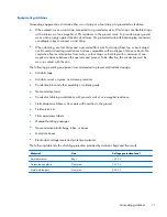
Electrostatic voltage levels and protective materials

The following table lists the shielding protection provided by antistatic bags and floor mats.

Material

Use

Voltage protection level

Antistatic plastics

Bags

1,500 V

Carbon-loaded plastic

Floor mats

7,500 V

Metallized laminate

Floor mats

5,000 V

Grounding guidelines

11

Summary of Contents for Slate7 3G

Page 1: ...oiceTab in Asia Pacific countries and regions and India and HP Slate7 3G in the People s Republic of China Maintenance and Service Guide IMPORTANT This document is intended for HP authorized service providers only ...

Page 2: ...s or omissions contained herein First Edition January 2014 Document Part Number 752188 001 Product notice This guide describes features that are common to most models Some features may not be available on your tablet Software terms By installing copying downloading or otherwise using any software product preinstalled on this tablet you agree to be bound by the terms of the HP End User License Agre...

Page 3: ...w another hard surface such as an adjoining optional printer or a soft surface such as pillows or rugs or clothing to block airflow Also do not allow the AC adapter to contact the skin or a soft surface such as pillows or rugs or clothing during operation The device and the AC adapter comply with the user accessible surface temperature limits defined by the International Standard for Safety of Inf...

Page 4: ...iv Safety warning notice ...

Page 5: ...inary requirements 8 Tools required 8 Service considerations 8 Plastic parts 8 Cables and connectors 8 Grounding guidelines 9 Electrostatic discharge damage 9 Packaging and transporting guidelines 10 Workstation guidelines 10 5 Removal and replacement procedures 12 Tablet component replacement procedures 12 Back cover 12 Middle frame 14 Battery 15 Power volume button board 16 Rear facing webcamera...

Page 6: ... light sensor board 26 6 Specifications 27 7 Updating apps widgets and the operating system 28 Factory data reset 28 8 Power cord set requirements 29 Requirements for all countries 29 Requirements for specific countries and regions 29 9 Recycling 31 Index 32 vi ...

Page 7: ...uid crystal display LCD air bond TouchScreen display panel with 5 point capacitive touch brightness 400 nits maximum Graphics Marvel GC100T Memory Supports 1 GB LP DDR2 Mass storage Supports a 16 GB eMMC solid state drive Audio and video Integrated forward facing stereo speakers 2 One microphone Stereo FM radio 5 0 MP autofocus rear facing webcamera 2 0 MP fixed focus front facing webcamera Sensor...

Page 8: ...02 11 b g n 2 4 GHz with 1 antenna Bluetooth 3 0 enhanced data rate EDR WWAN 3G data enable External expansion Integrated micro SD Card Reader expandable to 32 GB Ports Audio 3 5 mm headphone microphone combo jack supports North American type headset only Micro USB 2 0 supports charging Power requirements Supports a 4100 mAh Li ion battery non removable USB charging battery Supports an HP 10 W 5V ...

Page 9: ...entification Item Component Item Component 1 Rear facing webcamera 5 Front facing webcamera 2 Micro USB port 6 Microphone 3 Audio out headphone Audio in microphone jack 7 Volume control buttons 2 4 Speakers 2 8 Power button 3 ...

Page 10: ... country or region and then follow the on screen instructions Locating the product name and serial number The product name 1 and serial number 2 of your tablet are located on the battery You may need this information when you travel internationally or when you contact support Refer to Back cover on page 12 to remove the back cover and access this information 4 Chapter 3 Illustrated parts catalog ...

Page 11: ...a Left and right speakers cables and grommets 6b Vibrator module and cable 7 5 0 MP rear facing webcamera includes cable 751309 001 8 System board equipped with a Marvel PXA1088 1 20 GHz quad core processor 1 0 GB LP DDR2 system memory and a 16 0 GB eMMC solid state drive includes left and right speakers and vibrator module 751300 001 9 FPC cable includes double sided adhesive 751310 001 10 2 0 MP...

Page 12: ...or use only in Europe and South Korea includes duck head adapter 751300 001 System board equipped with a Marvel PXA1088 1 20 GHz quad core processor 1 0 GB LP DDR2 system memory and a 16 0 GB eMMC solid state drive includes left and right speakers and vibrator module 751301 001 7 in IPS LCD TouchScreen display panel assembly 751302 001 Back cover 751304 001 Middle frame 751305 001 Power volume but...

Page 13: ...d adhesive 751316 001 USB extension cable 751317 001 HP Slate7 VoiceTab equipped with a 7 in IPS LCD TouchScreen display panel a Marvel PXA1088 1 20 GHz quad core processor 1 0 GB LP DDR2 system memory and a 16 0 GB eMMC solid state drive 751657 001 USB extension cable Sequential part number listing 7 ...

Page 14: ...n damage plastic parts Use care when handling the plastic parts Apply pressure only at the points designated in the maintenance instructions Cables and connectors CAUTION When servicing the tablet be sure that cables are placed in their proper locations during the reassembly process Improper cable placement can damage the tablet Cables must be handled with extreme care to avoid damage Apply only t...

Page 15: ...e these precautions Keep components in their electrostatic safe containers until you are ready to install them Before touching an electronic component discharge static electricity by using the guidelines described in this section Avoid touching pins leads and circuitry Handle electronic components as little as possible If you remove a component place it in an electrostatic safe container The follo...

Page 16: ... proper materials are selected to avoid static charging When grounding is not possible use an ionizer to dissipate electric charges Workstation guidelines Follow these grounding workstation guidelines Cover the workstation with approved static shielding material Use a wrist strap connected to a properly grounded work surface and use properly grounded tools and equipment Use conductive field servic...

Page 17: ...m resistance between the operator and ground To be effective the conductive must be worn in contact with the skin The following grounding equipment is recommended to prevent electrostatic damage Antistatic tape Antistatic smocks aprons and sleeve protectors Conductive bins and other assembly or soldering aids Nonconductive foam Conductive tabletop workstations with ground cords of one megohm resis...

Page 18: ...nly parts There are as many as 20 screws that must be removed replaced and or loosened when servicing the tablet Make special note of each screw size and location during removal and replacement Back cover Description Spare part number Back cover 751302 001 7 in IPS LCD TouchScreen display panel assembly includes display panel cable and TouchScreen cable 751301 001 Before disassembling the tablet f...

Page 19: ...is caution can result in damage to the display panel surface 1 Place the tablet on a flat surface display panel side down with the power button and volume buttons facing away from you 2 Use the release notch 1 to release the bottom edge of the back cover 2 from the display panel assembly 3 Remove the back cover 3 Reverse this procedure to install the back cover Back cover 13 ...

Page 20: ...en shut it down through the operating system 2 Disconnect the power from the tablet by unplugging the power cord from the tablet 3 Disconnect all external devices from the tablet 4 Remove the back cover see Back cover on page 12 Remove the middle frame 1 Disconnect the battery cable from the system board 2 Remove the warranty sticker 1 that covers the system board retention screw 3 Remove the 14 P...

Page 21: ...e tablet by unplugging the power cord from the tablet 3 Disconnect all external devices from the tablet 4 Remove the back cover see Back cover on page 12 5 Remove the middle frame see Middle frame on page 14 WARNING To reduce potential safety issues use only the battery provided with the tablet a replacement battery provided by HP or a compatible battery purchased from HP CAUTION Removing a batter...

Page 22: ...these steps 1 Turn off the tablet If you are unsure whether the tablet is off or in Hibernation turn the tablet on and then shut it down through the operating system 2 Disconnect the power from the tablet by unplugging the power cord from the tablet 3 Disconnect all external devices from the tablet 4 Remove the back cover see Back cover on page 12 5 Remove the middle frame see Middle frame on page...

Page 23: ... follow these steps 1 Turn off the tablet If you are unsure whether the tablet is off or in Hibernation turn the tablet on and then shut it down through the operating system 2 Disconnect the power from the tablet by unplugging the power cord from the tablet 3 Disconnect all external devices from the tablet 4 Remove the back cover see Back cover on page 12 5 Remove the middle frame see Middle frame...

Page 24: ...on turn the tablet on and then shut it down through the operating system 2 Disconnect the power from the tablet by unplugging the power cord from the tablet 3 Disconnect all external devices from the tablet 4 Remove the back cover see Back cover on page 12 5 Remove the middle frame see Middle frame on page 14 Remove the WiFi antenna board 1 Disconnect the WiFi antenna board cable from the system b...

Page 25: ...u are unsure whether the tablet is off or in Hibernation turn the tablet on and then shut it down through the operating system 2 Disconnect the power from the tablet by unplugging the power cord from the tablet 3 Disconnect all external devices from the tablet 4 Remove the back cover see Back cover on page 12 5 Remove the middle frame see Middle frame on page 14 Remove the FPC cable 1 Disconnect t...

Page 26: ... the FPC cable make sure the alignment holes 1 on the main part of the FPC cable engage the alignment pins on the system board Also make sure the alignment holes 2 on the end of the FPC cable engage the alignment pins on the display panel assembly 20 Chapter 5 Removal and replacement procedures ...

Page 27: ...et by unplugging the power cord from the tablet 3 Disconnect all external devices from the tablet 4 Remove the back cover see Back cover on page 12 5 Remove the middle frame see Middle frame on page 14 6 Remove the FPC cable see FPC cable on page 19 Remove the speakers 1 Unsolder the speaker cables 1 from the system board terminals NOTE When installing the speakers the speaker red cables should be...

Page 28: ...y unplugging the power cord from the tablet 3 Disconnect all external devices from the tablet 4 Remove the back cover see Back cover on page 12 5 Remove the middle frame see Middle frame on page 14 6 Remove the FPC cable see FPC cable on page 19 Remove the vibrator module 1 Unsolder the vibrator module cables 1 from the system board terminals NOTE When installing the vibrator module the vibrator m...

Page 29: ...cord from the tablet 3 Disconnect all external devices from the tablet 4 Remove the back cover see Back cover on page 12 5 Remove the middle frame see Middle frame on page 14 6 Remove the FPC cable see FPC cable on page 19 Remove the system board 1 Disconnect the following cables from the system board 1 WiFi antenna board cable see WiFi antenna board on page 18 2 Power volume button board ZIF conn...

Page 30: ...ule are attached to the display panel assembly with double sided adhesive 3 Remove the six Phillips PM1 35 1 75 broad head screws 1 that secure the system board to the display panel assembly 4 Remove the system board 2 Reverse this procedure to install the system board 24 Chapter 5 Removal and replacement procedures ...

Page 31: ...l external devices from the tablet 4 Remove the back cover see Back cover on page 12 and then remove the following components a Middle frame see Middle frame on page 14 b FPC cable see FPC cable on page 19 c System board see System board on page 23 Remove the front facing webcamera 1 Turn the system board upside down with the top toward you 2 Release the ZIF connector 1 to which the front facing w...

Page 32: ...ll external devices from the tablet 4 Remove the back cover see Back cover on page 12 and then remove the following components a Middle frame see Middle frame on page 14 b FPC cable see FPC cable on page 19 c System board see System board on page 23 Remove the proximity ambient light sensor board 1 Detach the proximity ambient light sensor board from the display panel assembly The proximity ambien...

Page 33: ...ing an industry standard micro A or micro B USB cable The HP adapter included with your voice tablet is recommended for charging the voice tablet Temperature Operating 5 C to 35 C 41 F to 95 F Nonoperating 20 C to 60 C 4 F to 140 F Relative humidity non condensing Operating 10 to 90 Nonoperating 5 to 95 Maximum altitude unpressurized Operating 15 m to 3 048 m 50 ft to 10 000 ft Nonoperating 15 m t...

Page 34: ...widgets might not work well with the most recent operating system Go to the QQ App store to download the latest versions of HP and third party apps and widgets The QQ App store displays the number of existing applications that you can update If you want to update the operating system manually go to http www hp com support Factory data reset To reset all settings and delete all data on the device 1...

Page 35: ...t 1 0 m 3 3 ft and no more than 2 0 m 6 5 ft All power cord sets must be approved by an acceptable accredited agency responsible for evaluation in the country or region where the power cord set will be used The power cord sets must have a minimum current capacity of 10 amps and a nominal voltage rating of 125 or 250 V AC as required by the power system of each country or region The appliance coupl...

Page 36: ...5P 15 A 250 V configuration 3 The appliance coupler flexible cord and wall plug must bear a T mark and registration number in accordance with the Japanese Dentori Law The flexible cord must be Type VCT or VCTF 3 conductor 1 00 mm conductor size The wall plug must be a two pole grounding type with a Japanese Industrial Standard C8303 7 A 125 V configuration 4 The flexible cord must be Type RVV 3 co...

Page 37: ...e battery in general household waste Follow the local laws and regulations in your area for battery disposal HP encourages customers to recycle used electronic hardware HP original print cartridges and rechargeable batteries For more information about recycling programs see the HP Web site at http www hp com recycle 31 ...

Page 38: ...ent 11 grounding 9 packaging 10 transporting 10 workstation 10 H headphone jack 3 J jacks audio in 3 audio out 3 headphone 3 microphone 3 M mass storage device product description 1 memory module product description 1 microphone location 3 product description 1 microphone jack 3 middle frame removal 14 spare part number 5 6 14 model name 1 N networking product description 2 O operating system prod...

Page 39: ... 6 21 22 speakers location 3 removal 21 spare part number 5 6 21 system board removal 23 spare part number 5 6 23 T tablet major components 5 spare part number 6 7 specifications 27 tools required 8 transporting guidelines 10 U USB extension cable spare part number 6 7 USB port 3 V vibrator module removal 22 spare part number 5 6 22 video product description 1 volume control buttons 3 W webcamera ...

Reviews: