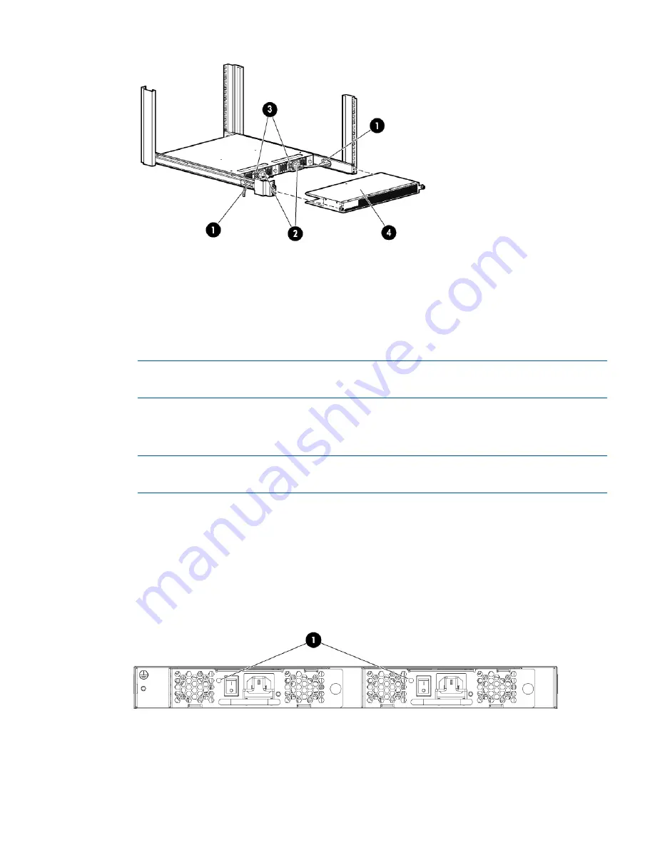
Figure 11 Connecting power and installing the plenum
3. Power switches
1. Cutouts for power cords
4. Plenum thumb screws
2. Power cable plugs
7.
Connect the other end of the power cords to power sources on separate circuits to protect
against AC failure. (Make sure that two power cords are connected to the SN6000B 48-port
switch and one power cord is connected to the SN3000B 24–port switch.)
NOTE:
If you are configuring the second (optional) power supply, the SN3000B switch will
also have two power cords.
8.
Power on the power supplies by setting both power switches to the ON (
I
) position.
The power supply LEDs are amber until the POST is complete, and then change to green. See
Figure 12 (page 23)
. The switch takes several minutes to boot and complete POST.
NOTE:
When installed, the plenum covers the power supply switches and LEDs. However,
the LEDs are visible through the air holes in the front of the plenum.
9.
Slide the plenum over the nonport side of the inner rails, taking care to bypass the power
cables. See
Figure 11 (page 23)
.
10. Tighten the thumbscrews to secure the plenum to the front of the rack.
11. Verify that the switch power and status LEDs on the port side of the switch are green. See
Figure 13 (page 24)
.
12. Proceed to
“Setting up the switch” (page 24)
.
Figure 12 Power supply and fan assembly LEDs
1. Power supply/fan assembly status LEDs
Installing the switch
23
Summary of Contents for SN3000B
Page 6: ...Grounding methods 66 Glossary 67 Index 69 6 Contents ...
Page 54: ...Japanese notices Japanese VCCI A notice 54 Regulatory compliance notices ...
Page 57: ...Dutch laser notice French laser notice German laser notice Laser compliance notices 57 ...
Page 64: ...German battery notice Italian battery notice 64 Regulatory compliance notices ...
Page 65: ...Japanese battery notice Spanish battery notice Battery replacement notices 65 ...
Page 68: ...UTC Coordinated Universal Time VF Virtual Fabric WWN World Wide Name 68 Glossary ...


