background image

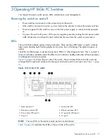
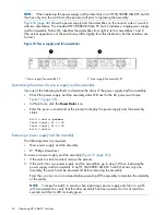
The nonport side of the switch has one LED per power supply/fan assembly. See

Figure 17 (page

37)

. The standard configuration of the HP SN3000B 16Gb FC Switch includes a single power

supply/fan assembly.

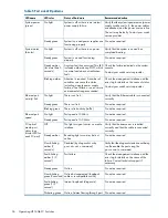
Table 6 (page 37)

describes the status.

Figure 17 Power supply/fan status LEDs

1. Power supply/fan assembly status LED

Table 6 Nonport side LED patterns

Recommended action

Status of hardware

LED color

LED name

Verify the power supply/fan is on and
seated and the power cord is connected to
a functioning power source.

Power supply/fan is not receiving
power or is off.

No light

Power
supply/fan
assembly status

No action required.

Power supply/fan is operating
normally.

Steady green

Check the power cable connection. Verify
that the power supply/fan is powered on.
Replace the power supply/fan FRU.

Power supply/fan is faulty.

When the switch is first powered on
the power supply/fan status LED is

Flashing green

flashing green until POST is
complete.

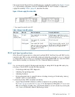
POST and boot specifications

When the switch is powered on or rebooted, it performs POST. Total boot time with POST can be
several minutes. POST can be omitted after subsequent reboots by using the

fastboot

command

or entering the

diagDisablePost

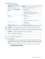
command to persistently disable POST. For more information

about these commands, see the Fabric OS 7.0.x Command Reference Manual.

POST

You can monitor the results of the diagnostic tests that run during POST through LED activity, the
error log, or the CLI. POST includes the following tasks:

Conducting preliminary POST diagnostics

Initializing the operating system

Initializing hardware

Running diagnostic tests on several functions, including circuitry, port functionality, memory,
statistics counters, and serialization

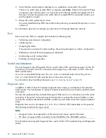
To determine whether POST completed successfully:
1.

Inspect the switch LEDs to determine whether components are operating properly.

See

Table 5 (page 36)

and

Table 6 (page 37)

for descriptions of LED patterns. If one or more

LEDs do not display a healthy state, verify that the LEDs are not set to beacon by entering the

switchshow

command to detect if beaconing is active.

POST and boot specifications

37

Summary of Contents for SN3000B

Page 1: ...information on installing configuring and maintaining the HP SN6000B Fibre Channel Switch and the HP SN3000B Fibre Channel Switch It is intended for system administrators and technicians with knowledge of SANs and HP FC switches HP Part Number 5697 1522 Published March 2012 Edition 2 ...

Page 2: ...al license The information contained herein is subject to change without notice The only warranties for HP products and services are set forth in the express warranty statements accompanying such products and services Nothing herein should be construed as constituting an additional warranty HP shall not be liable for technical or editorial errors or omissions contained herein Acknowledgements Wind...

Page 3: ...s 17 Cabling considerations 18 Installing the switch 18 Items required for installation 18 Installing the switch in a rack using the Rack Mount Kit 19 Installing a standalone switch 24 Setting up the switch 24 Connecting the serial cable 25 Logging in to the serial console port 25 Setting the IP address 25 Using DHCP to set the IP address 26 Setting a static IP address 26 Setting the date and time...

Page 4: ...y 44 Typographic conventions 45 Customer self repair 45 A Specifications 46 Physical specifications 46 Facility requirements 46 Power supply specifications 46 Environmental requirements 47 General specifications 48 Data transmission ranges 48 Memory specifications 49 FC port specifications 49 Serial port specifications 49 AG default port mapping 50 B Regulatory compliance notices 51 Regulatory com...

Page 5: ...ce 59 Bulgarian recycling notice 59 Czech recycling notice 59 Danish recycling notice 59 Dutch recycling notice 59 Estonian recycling notice 60 Finnish recycling notice 60 French recycling notice 60 German recycling notice 60 Greek recycling notice 60 Hungarian recycling notice 60 Italian recycling notice 61 Latvian recycling notice 61 Lithuanian recycling notice 61 Polish recycling notice 61 Port...

Page 6: ...Grounding methods 66 Glossary 67 Index 69 6 Contents ...

Page 7: ...censes can be purchased The switch provides excellent value as the foundation of a SAN and can grow to meet an organization s SAN needs The HP SN6000B 16Gb FC Switch can be configured in AG mode which enables configuring the enterprise fabric to handle additional N_Ports instead of domains Reducing the number of domain IDs and ports simplifies configuration and management in a large fabric Switche...

Page 8: ...rdware zoning permits or denies delivery of frames to any destination port address Extensive diagnostics and system monitoring capabilities for enhanced high RAS 10 Gb s FC integration on the same port provides DWDM metro connectivity on the same switch can be done on the first eight ports only Real time power monitoring enables monitoring the fabric power usage at a switch level Port to port late...

Page 9: ...unctional Nonport side of the switch Figure 2 page 9 shows the nonport side of the HP SN6000B 16Gb FC Switch which contains two power supply and fan assemblies each including an AC power receptacle and AC power switch Figure 2 Nonport side view of the HP SN6000B 16Gb FC Switch 2 Airflow label 1 Power supply fan assembly 2 4 Power supply and fan assembly LED 3 Power supply and fan assembly 1 6 Powe...

Page 10: ... ports on the HP SN6000B 16Gb FC Switch can be used as a trunking group to achieve speeds of up to 128 Gb s 256 Gb s full duplex for optimal bandwidth utilization and load balancing For example the FC ports on the SAN Switch are numbered from left to right and color coded in groups of eight to indicate which ports you can combine into trunking groups Figure 3 page 10 shows the switch with three tr...

Page 11: ...ti mode Optical Cable BK843A 1m HP PremierFlex OM4 LC LC Multi mode Optical Cable QK732A HP PremierFlex OM4 Fiber Optic Cables 2m HP PremierFlex OM4 LC LC Multi mode Optical Cable QK733A 5m HP PremierFlex OM4 LC LC Multi mode Optical Cable QK734A 15m HP PremierFlex OM4 LC LC Multi mode Optical Cable QK735A 30m HP PremierFlex OM4 LC LC Multi mode Optical Cable QK736A 50m HP PremierFlex OM4 LC LC Mu...

Page 12: ...ansparent to the host and the fabric You can increase the number of hosts that have access to the fabric without increasing the number of switches Platform capabilities The HP SN3000B 16Gb FC Switch offers the following features and capabilities Up to 24 autosensing ports of high performance 16 Gbps technology in a single domain POD scaling from 12 to 24 ports 4 8 and 16 Gbps autosensing FC switch...

Page 13: ...tory default restoration The integral LEDs remain unlit at all times A USB port that provides storage for firmware updates supportsave command output and storage for configuration uploads and downloads One power supply and fan assembly in the base model There are two fans per assembly An optional second power supply and fan assembly is available for redundancy and hot swap capability One LED green...

Page 14: ... series 8 24 Port SAN Switch ISL Trunking LTU HP SN3000B 16Gb 24 12 Fibre Channel Switch 12 port Upgrade LTU NOTE For the latest information on supported software components see the product QuickSpecs available from the HP website http www hp com go sn3000b quickspecs ISL Trunking ISL Trunking is optional software that enables creating trunking groups of ISLs between adjacent switches Up to eight ...

Page 15: ...ble AJ839A 0 5m HP PremierFlex OM3 LC LC Multi Mode Optical Cable BK837A HP PremierFlex OM3 Optical Cables 1m HP PremierFlex OM3 LC LC Multi mode Optical Cable BK838A 2m HP PremierFlex OM3 LC LC Multi mode Optical Cable BK839A 5m HP PremierFlex OM3 LC LC Multi mode Optical Cable BK840A 15m HP PremierFlex OM3 LC LC Multi mode Optical Cable BK841A 30m HP PremierFlex OM3 LC LC Multi mode Optical Cabl...

Page 16: ...nsceivers Table 4 SFP transceiver options Part number Option AJ716B HP 8Gb Shortwave B series FC SFP 8 Gb Transceivers AJ717A HP 8Gb LW B series 10km FC SFP AW538A HP B series 8Gb LW 25km FC SFP QK724A HP B series 16Gb SFP Short Wave Transceiver 16 Gb Transceivers QK725A HP 16Gb Long Wave B series 10km FC SFP 1 Pack 16 Gb Long Wave Transceivers 16 HP 16Gb FC Switches ...

Page 17: ... mounting hardware and plenum HP product documentation including Read Me First Safety Guides User License and Warranty Brocade EZ Switch and China ROHS documentation HP SAN Network Advisor DVD Installation and safety considerations You can install the switch in a rack or as a standalone device on a flat surface HP highly recommends mounting the switch in an HP 10000 Series Rack Electrical consider...

Page 18: ...rtent movement of the rack and helps prevent the cables from being bent to less than the minimum bend radius If you are using ISL Trunking consider grouping cables by trunking groups The cables used in trunking groups must meet specific requirements as described in the Fabric OS Administrator s Guide For easier maintenance label the fiber optic cables and record the devices to which they are conne...

Page 19: ...to draw cooler air from outside the rack rather than drawing in heated air from within the rack Provides room for a gradual bend in the fiber optic cables because the port side of the switch is set back from the edge of the rack Use only the screws provided in the Rack Mount Kit Using other screws can cause damage to internal components Installation safety guidelines Verify that the rack and the a...

Page 20: ...ewed from its nonport side Figure 7 Attaching the inner rails to the switch 2 Take care to select a mounting location in the rack such that the cutouts in the sides of each rail are not obstructed You will route the switch power cords through these holes later in this procedure 3 Attach each rear mounting bracket to a rear rack upright column using two Phillips screws and adapter washers See Figur...

Page 21: ... the rear mounting brackets b Attach the front of the rail to a front rack upright column using two Phillips screws and adapter washers c Attach the outer rail to the rear mounting bracket using a Phillips screw TIP Tighten the rear screws just enough for the end of the screw to go through the rear brackets Later in the procedure you will need room to slide the inner rail between the screw head an...

Page 22: ...talling the switch in the rack 6 At the front of the rack run the switch power cords from the sides of the rack through the cutouts in the rail and then connect them to the switch power supplies Connect two power cords to the SN6000B 48 port switch Connect one power cord to the SN3000B 24 port switch See Figure 1 1 page 23 IMPORTANT Make sure that the power cords do not come in contact with any sh...

Page 23: ...on The power supply LEDs are amber until the POST is complete and then change to green See Figure 12 page 23 The switch takes several minutes to boot and complete POST NOTE When installed the plenum covers the power supply switches and LEDs However the LEDs are visible through the air holes in the front of the plenum 9 Slide the plenum over the nonport side of the inner rails taking care to bypass...

Page 24: ...r supplies if an optional second power supply is present Then connect the power cords to power sources on separate circuits to protect against AC failure NOTE If you are configuring the second optional power supply on the SN3000B switch it will also have two power cords Ensure that the cords have a minimum service loop of 6 inches available and are routed to avoid stress 5 Power on the power suppl...

Page 25: ...f ttyb is already in use enter tip dev ttya 9600 Logging in to the serial console port 1 Verify that the switch has completed POST When POST is complete the switch status and switch power LEDs return to a normal state 2 When the terminal emulator stops reporting information press Enter to display the login prompt 3 Log in to the switch as admin using the default password password You are prompted ...

Page 26: ... Ethernet subnetmask 192 0 2 38 Gateway IP address 192 0 2 172 3 Verify the IP address by entering the ipaddrshow command at the prompt 4 Record the IP address on the pull out tab on the port side of the switch 5 When prompted enter off to disable DHCP DHCP OFF off 6 If the serial port is no longer required use the logout command to log out of the serial console Remove the serial cable and replace...

Page 27: ...o parameters displays the current time zone setting The tstimezone interactive command displays all time zones supported in the firmware The timeZone_fmt command sets the time zone based on the country and city or a time zone ID such as PST that you enter This command requires administrator privileges The time zone setting has the following characteristics Automatically adjusts for Daylight Saving...

Page 28: ...y By default this value is the local clock server LOCL of the principal or primary FCS switch Changes to the clock server value on the principal or primary FCS switch are propagated to all switches in the fabric When a switch has been added to the fabric the time server daemon of the principal or primary FCS switch sends the addresses of all existing clock servers and the time to that switch If a ...

Page 29: ...d IPv6 considerations see the Fabric OS Administrator s Guide Configuring the zones and selecting devices See the Network Advisor User Manual available from the storage section of the HP website http www hp com support manuals Connecting devices The Connect Devices window shows a graphical representation of the switch with the device connections based on the information that you entered in Configu...

Page 30: ...n Insert an SFP transceiver into the lower row of ports with the gold edge up a Remove any protector plugs from the SFP transceiver Insert each SFP transceiver right side up in the top row of ports and upside down in the bottom row of ports until it is firmly seated and the latching mechanism clicks The 16 Gb s SFP transceiver does not have a bail Use the pull tab to push the transceiver into the ...

Page 31: ...and The following example shows the default settings of 2 and 0 for DOWN and MARGINAL units for both Bad Power Supplies and Bad Fans switch admin switchstatuspolicyset some output skipped The minimum number of Bad PowerSupplies contributing to DOWN status 0 2 2 Bad PowerSupplies contributing to MARGINAL status 0 2 0 some output skipped Bad Fans contributing to DOWN status 0 2 2 Bad Fans contributi...

Page 32: ... information on this command see the Fabric OS 7 0 x Command Reference Manual 2 Obtain the WWN from the Switch ID pull out tab located on the port side of your switch You can also use the switchshow command to display the WWN 3 Contact your HP representative to purchase the appropriate Port Upgrade license HP requires the switch WWN obtained in Step 2 to assign a license key 4 Install the license ...

Page 33: ... whether the switch is configured in AG or Native mode For a list of available features for each mode see the Access Gateway Administrator s Guide In AG mode cascading is not available for the switch See the Access Gateway Administrator s Guide for details on any restrictions In Native mode the SN6000B switch provides up to 48 external FC ports and the SN3000B switch provides up to 24 external FC ...

Page 34: ...nable AG mode 5 Enter the ag modeshow command to verify that AG mode is enabled switch admin ag modeshow Access Gateway mode is enabled Disabling AG mode When you disable AG mode the switch reboots automatically and comes back online using the fabric switch configuration The AG parameters such as F_Port to N_Port mapping Failover and Failback are removed automatically When the switch reboots it st...

Page 35: ...ing light Flashing lights can be slow fast or flickering The lights are green or amber The LEDs can flash green or amber during boot POST or other diagnostic tests This is normal it does not indicate a problem unless the LEDs do not indicate a healthy state after all boot processes and diagnostic tests are complete Figure 16 page 35 shows the port side of the switch The port status LEDs for the FC...

Page 36: ...r more environmental ranges exceeded Verify that the Ethernet cable is connected correctly There is no link No light Ethernet port activity link No action required There is a link Steady green No action required There is link activity traffic Blinking green No action required Port speed is 10 Mb s No light Ethernet port speed No action required Port speed is 100 Mb s Steady green Verify that the t...

Page 37: ...nd boot specifications When the switch is powered on or rebooted it performs POST Total boot time with POST can be several minutes POST can be omitted after subsequent reboots by using the fastboot command or entering the diagDisablePost command to persistently disable POST For more information about these commands see the Fabric OS 7 0 x Command Reference Manual POST You can monitor the results o...

Page 38: ...onnections the switch uses SFP transceivers that support any combination of SWL LWL and ELWL optical media If you use an unqualified transceiver the switchshow command output shows the port in a Mod_Inv state Fabric OS also logs the issue in the system error log For information about installing transceivers see Connecting devices page 29 Diagnostic tests In addition to POST Fabric OS includes diag...

Page 39: ...ecial tools are required to remove and replace this FRU The switch will continue to operate during the FRU replacement if you follow the procedures in this chapter Replacing a power supply and fan assembly takes less than two minutes CAUTION Disassembling any part of the power supply voids the part warranty and regulatory certifications There are no user serviceable parts inside the power supply a...

Page 40: ... power switch see Figure 17 page 37 In Web Tools click the Power Status icon Enter the psshow command at the prompt to display the power supply and fan assembly status br6510 admin psshow Power Supply 1 is OK Power Supply 2 is OK br6510 admin Removing a power supply and fan assembly The following items are required New power supply and fan assembly 1 Phillips screwdriver To remove a power supply a...

Page 41: ...nd fan assembly being replaced 5 Unscrew the captive screw using a Phillips screwdriver 6 Remove the power supply and fan assembly by pulling the handle out and away from the chassis 7 Note the product and airflow labels or their absence on the assembly just removed Figure 19 Replacing the power supply and fan assembly 2 Power supply and fan assembly 1 Switch chassis 4 Product and airflow labels 3...

Page 42: ...o the chassis until it is firmly seated 4 Using the Phillips screwdriver secure the power supply and fan assembly to the chassis by tightening the captive screw 5 Plug the power cord into the power supply and fan assembly and power on the unit by setting the AC power switch to the on I position 6 Verify that the LED on the new power supply and fan assembly displays a steady green light while the s...

Page 43: ... message to storagedocsFeedback hp com All submissions become the property of HP Related information The following documents provide related information See the appropriate document version for your operating environment Network Advisor User Manual Fabric OS 7 0 x Administrator s Guide Fabric OS 7 0 x Command Reference Manual SAN TECH NOTE Preparing to Install the Access Gateway Access Gateway Adm...

Page 44: ... protects personnel and equipment WARNING To reduce the risk of personal injury or damage to equipment Extend leveling jacks to the floor Ensure that the full weight of the rack rests on the leveling jacks Install stabilizing feet on the rack In multiple rack installations fasten racks together securely Extend only one rack component at a time Racks can become unstable if more than one component i...

Page 45: ...ld text WARNING Indicates that failure to follow directions could result in bodily harm or death CAUTION Indicates that failure to follow directions could result in damage to equipment or data IMPORTANT Provides clarifying information or specific instructions NOTE Provides additional information TIP Provides helpful hints and shortcuts Customer self repair HP CSR programs allow you to repair your ...

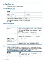
Page 46: ...vailable in the immediate vicinity of the switch Ambient air temperature not exceeding 40 C 104 F while the switch is operating Cabinet rack mounted 1U in a 48 3 cm 19 in cabinet Use rack kits designed for the extra width of the switch to mount in standard cabinets racks All equipment in cabinet grounded through a reliable branch circuit connection Plenum installed to prevent overheating Additiona...

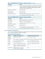
Page 47: ...C Single power supply output AC lines are fused Input line protection 80 W with all 24 ports populated with 16 Gb s SWL optical media System power consumption 60 W with empty chassis and no optical media Environmental requirements Table 13 page 47 lists the acceptable environmental ranges for both operating and nonoperating such as during transportation or storage conditions Table 13 Environmental...

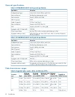
Page 48: ... architecture PowerPC 440EPx at 667 MHz System processor FC PH ANSI FC protocol FC Class 2 and Class 3 Modes of operation Complies with FC SW 3 Rev 6 6 Fabric initialization Complies with FC IP 2 3 of FCA profile FC IP 384 Gb s Aggregate switch I O bandwidth 800 ns with no contention destination port is free FC port to port latency An aggregate switching capacity of 210 million frames per second f...

Page 49: ...ndards see Regulatory compliance notices page 51 The ports operate at 2 4 8 or 16 Gb s depending on SFP models and are able to autonegotiate to the maximum link speed NOTE HP does not support 2 Gb s connectivity to the HP SN6000B 16Gb FC Switch or the HP SN3000B 16Gb FC Switch Serial port specifications The serial port is located on the port side of the switch and uses an RJ 45 connector for the s...

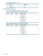
Page 50: ...N_Ports F_Ports Total ports 0 4 mapped to 40 40 47 0 39 48 5 9 mapped to 41 10 14 mapped to 42 15 19 mapped to 43 20 24 mapped to 44 25 29 mapped to 45 30 34 mapped to 46 35 39 mapped to 47 Table 20 HP SN3000B 16Gb FC Switch AG default port mapping Default port mapping N_Ports F_Ports Total ports 0 1 mapped to 16 16 23 0 15 24 2 3 mapped to 17 4 5 mapped to 18 6 7 mapped to 19 8 9 mapped to 20 10 ...

Page 51: ...s to bear a label indicating the interference potential of the device as well as additional operating instructions for the user FCC rating label The FCC rating label on the device shows the classification A or B of the equipment Class B devices have an FCC logo or ID on the label Class A devices do not have an FCC logo or ID on the label After you determine the class of the device refer to the cor...

Page 52: ... this device that are not expressly approved by Hewlett Packard Company may void the user s authority to operate the equipment Cables When provided connections to this device must be made with shielded cables with metallic RFI EMI connector hoods in order to maintain compliance with FCC Rules and Regulations Canadian notice Avis Canadien Class A equipment This Class A digital apparatus meets all r...

Page 53: ...disclaimer In no event do the EPUP logos shown on the product and FRUs alter or expand that warranty that Brocade provides with respect to its products as set forth in the applicable contract between Brocade and its customer Brocade hereby disclaims all other warranties and representations with respect to the information contained on this CD including the implied warranties of merchantability fitn...

Page 54: ...Japanese notices Japanese VCCI A notice 54 Regulatory compliance notices ...

Page 55: ...device obtained EMC registration for office use Class A and may be used in places other than home Sellers and or users need to take note of this Class B equipment Taiwanese notices BSMI Class A notice This is Class A product In a domestic environment this product may cause radio interference in which case the user may be required to take adequate measures Korean notices 55 ...

Page 56: ...laser product s installation guide may result in hazardous radiation exposure To reduce the risk of exposure to hazardous radiation Do not try to open the module enclosure There are no user serviceable components inside Do not operate controls make adjustments or perform procedures to the laser device other than those specified herein Allow only HP Authorized Service technicians to repair the unit...

Page 57: ...Dutch laser notice French laser notice German laser notice Laser compliance notices 57 ...

Page 58: ...Italian laser notice Japanese laser notice Spanish laser notice 58 Regulatory compliance notices ...

Page 59: ...vropské unii Tento symbol znamená že nesmíte tento produkt likvidovat spolu s jiným domovním odpadem Místo toho byste měli chránit lidské zdraví a životní prostředí tím že jej předáte na k tomu určené sběrné pracoviště kde se zabývají recyklací elektrického a elektronického vybavení Pro více informací kontaktujte společnost zabývající se sběrem a svozem domovního odpadu Danish recycling notice Bor...

Page 60: ...es ménagères German recycling notice Entsorgung von Altgeräten von Benutzern in privaten Haushalten in der EU Dieses Symbol besagt dass dieses Produkt nicht mit dem Haushaltsmüll entsorgt werden darf Zum Schutze der Gesundheit und der Umwelt sollten Sie stattdessen Ihre Altgeräte zur Entsorgung einer dafür vorgesehenen Recyclingstelle für elektrische und elektronische Geräte übergeben Weitere Info...

Page 61: ...ku veselības un vides aizsardzību nododot lietoto aprīkojumu otrreizējai pārstrādei īpašā lietotu elektrisko un elektronisko ierīču savākšanas punktā Lai iegūtu plašāku informāciju lūdzu sazinieties ar savu mājsaimniecības atkritumu likvidēšanas dienestu Polish recycling notice Utylizacja zużytego sprzętu przez użytkowników w prywatnych gospodarstwach domowych w krajach Unii Europejskiej Ten symbo...

Page 62: ...dení Ďalšie informácie získate od spoločnosti zaoberajúcej sa likvidáciou domového odpadu Spanish recycling notice Eliminación de los equipos que ya no se utilizan en entornos domésticos de la Unión Europea Este símbolo indica que este producto no debe eliminarse con los residuos domésticos En lugar de ello debe evitar causar daños a la salud de las personas y al medio ambiente llevando los equipo...

Page 63: ...Battery replacement notices Dutch battery notice French battery notice Battery replacement notices 63 ...

Page 64: ...German battery notice Italian battery notice 64 Regulatory compliance notices ...

Page 65: ...Japanese battery notice Spanish battery notice Battery replacement notices 65 ...

Page 66: ...touching a static sensitive component or assembly Grounding methods There are several methods for grounding Use one or more of the following methods when handling or installing electrostatic sensitive parts Use a wrist strap connected by a ground cord to a grounded workstation or computer chassis Wrist straps are flexible straps with a minimum of 1 megohm 10 percent resistance in the ground cords ...

Page 67: ...ting FCS Fabric Configuration Server FICON Fibre Connection or Fibre Connectivity FRU Field replaceable unit FTP File Transfer Protocol GMT Greenwich Mean Time HBA Host Bus Adapter ISL Inter Switch Link LC Lucent connector LWL Long Wavelength NPIV N_Port ID Virtualization NTP Network Time Protocol server OM3 Optical Multimode 3 PN Part Number POD Ports on Demand POST Power on self test QoS Quality...

Page 68: ...UTC Coordinated Universal Time VF Virtual Fabric WWN World Wide Name 68 Glossary ...

Page 69: ...6Gb FC Switch hardware options 1 1 nonport side components 9 overview 7 platform capabilities 7 platform components 8 port side view 9 software options 9 I installing and configuring the switch 17 ISL trunking groups HP SN3000B 16Gb FC Switch 14 HP SN6000B 16Gb FC Switch 10 J Japanese notices 54 K Korean notices 55 L laser compliance notices 56 licenseadd command 32 licenseshow command 32 O option...

Page 70: ...y 31 Subscriber s Choice HP 43 switch status policy 31 symbols in text 45 T Taiwanese notices 55 technical support HP 43 service locator website 44 text symbols 45 W warning rack stability 44 websites customer self repair 45 HP 44 HP Subscriber s Choice for Business 43 product manuals 43 70 Index ...

Reviews: