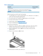
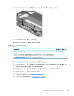
Power button board
Description
Spare part number
Power button board
NOTE:
The power button board does not include the power button board cable. The power
button board cable is included in the Cable Kit, spare part number 736883-001. See
Cable Kit
on page 21
for more Cable Kit spare part information.
736889-001
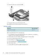
Before removing the power button board, follow these steps:
1.
Turn off the tablet. If you are unsure whether the tablet is off or in Hibernation, turn the tablet on,
and then shut it down through the operating system.
2.
Disconnect the power from the tablet by unplugging the power cord from the tablet.
3.
Disconnect all external devices from the tablet.
4.
Remove the back cover (see
Back cover on page 34
).
5.
Remove the tablet battery (see
Tablet battery on page 36
).
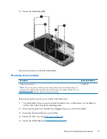
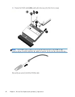
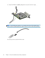
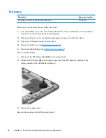
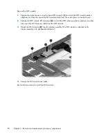
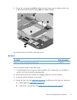
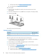
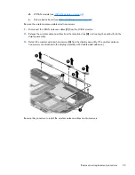
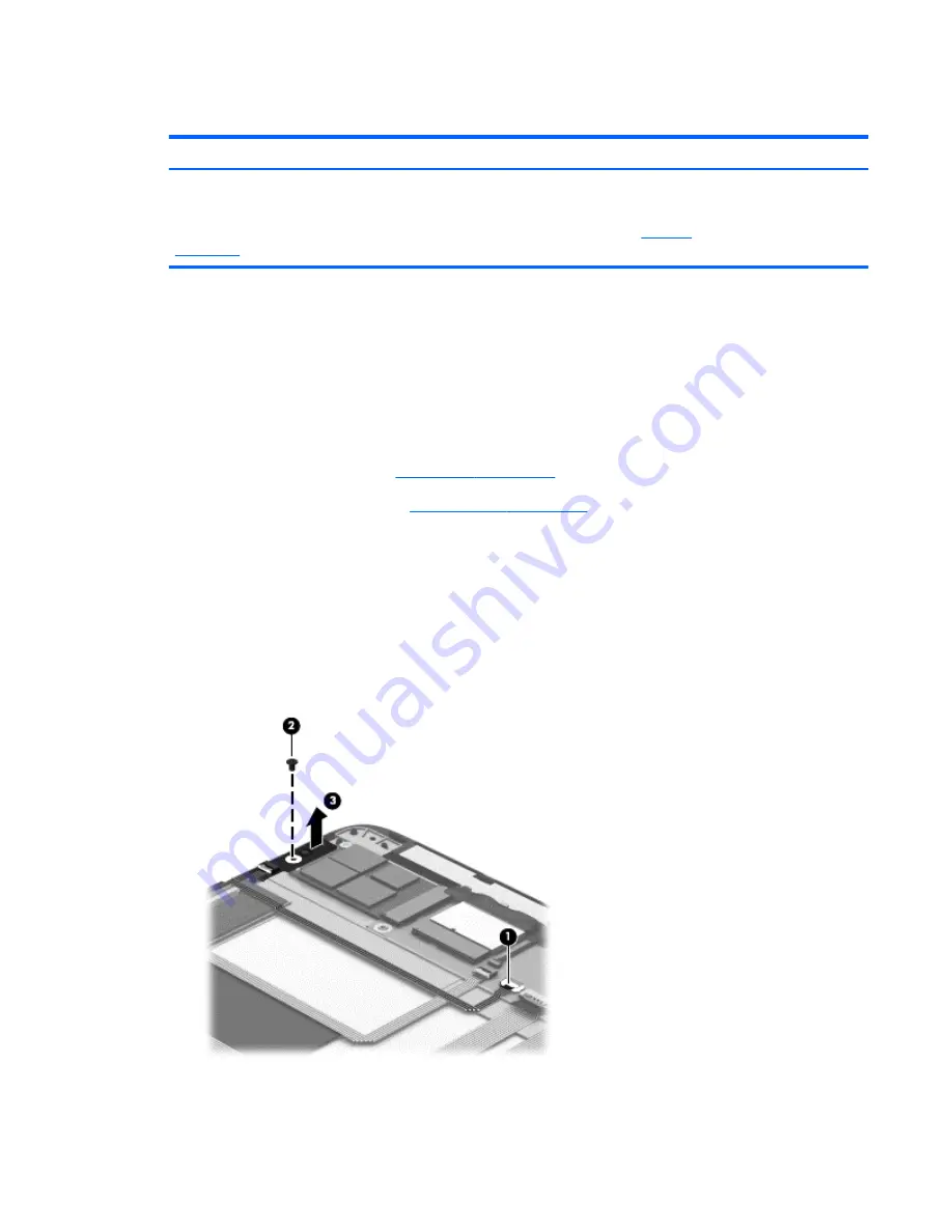
Remove the power button board:
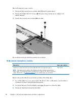
1.
Release the zero insertion force (ZIF) connector
(1)
to which the power button board cable is
attached, and then disconnect the power button board cable from the system board.
2.
Remove the Phillips PM2.0×3.0 screw
(2)
that secures the power button board to the
display assembly.
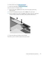
3.
Remove the power button board
(3)
and cable.
Reverse this procedure to install the power button board.
Removal and replacement procedures
45