


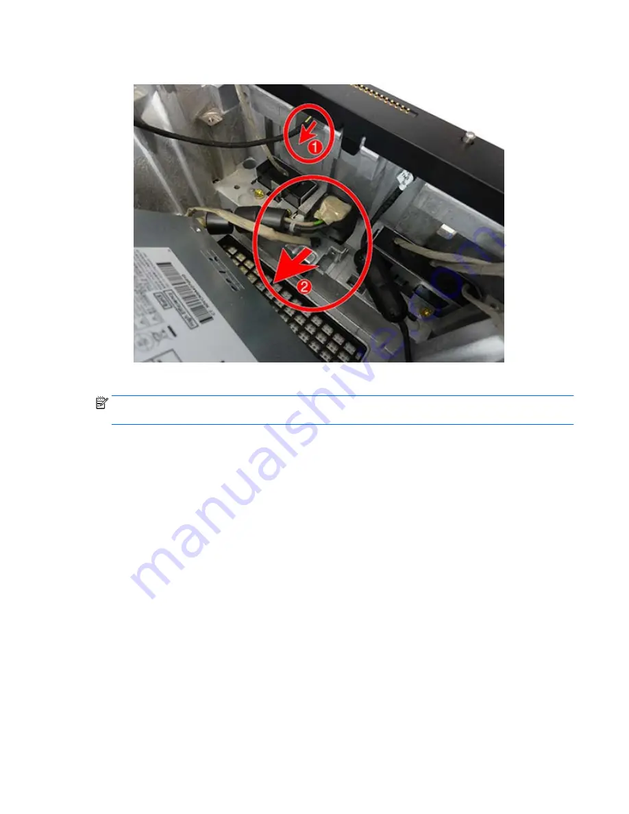
13.
Disconnect the small cable from the POGO board
(1)
, and slide the power connector from the slot
(2)
.
To install the power supply, reverse the removal procedures.
NOTE:
When connecting the antennas cables, connect the cable labeled “1” to the MAIN connector on the
module and the cable labeled “2” to the AUX connector on the module.
ENWW
Power supply 101
Summary of Contents for Sprout
Page 1: ...Maintenance Service Guide Sprout Business PC ...
Page 4: ...iv About This Book ENWW ...
Page 10: ...x ENWW ...
Page 20: ...10 Chapter 1 Getting to know your Sprout ENWW ...
Page 34: ...24 Chapter 3 Disassembly preparation and SATA drive guidelines ENWW ...
Page 86: ...76 Chapter 4 Removal and Replacement Procedures Computer ENWW ...
Page 116: ...106 Chapter 5 Removal and Replacement Procedures Column ENWW ...
Page 128: ...118 Chapter 6 Computer Setup F10 Utility ENWW ...
Page 138: ...128 Chapter 8 Troubleshooting ENWW ...
Page 158: ...148 Chapter 11 Password security and resetting CMOS ENWW ...
Page 162: ...152 Chapter 12 Maintaining peak performance ENWW ...
Page 168: ...158 Appendix C Specifications ENWW ...
Page 172: ...WLAN module illustrated 12 removing 49 162 Index ENWW ...


