6.
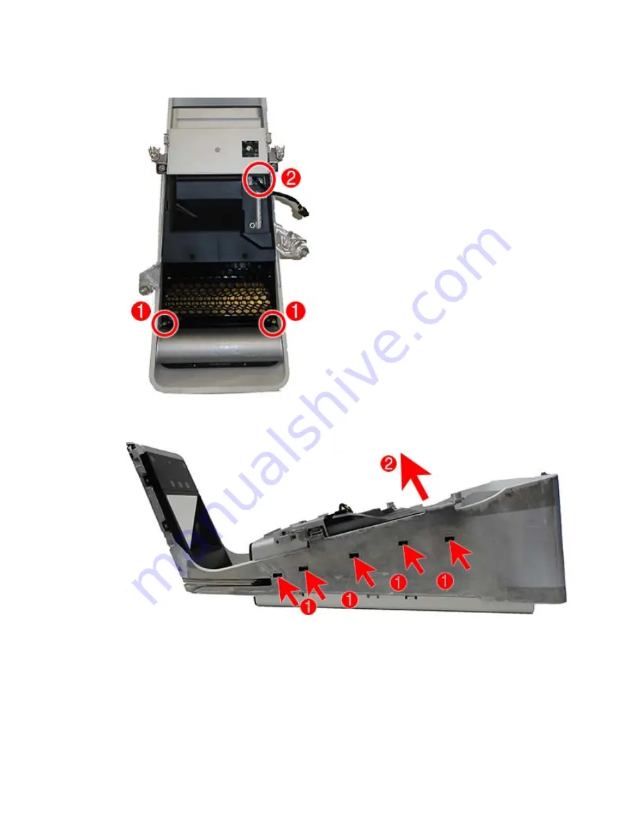
Remove the two Torx screws that secure the cover to the column
(1)
. Note the power supply cable
routes through a hole in the front of the cover
(2)
.
7.
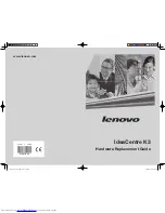
Use a flat tool to disengage the tabs that secure the cover to the column
(1)
, and the lift the cover off
the column
(2)
.
To install the inside cover, reverse the removal procedures.
88
Chapter 5 Removal and Replacement Procedures – Column
ENWW
Summary of Contents for Sprout
Page 1: ...Maintenance Service Guide Sprout Business PC ...
Page 4: ...iv About This Book ENWW ...
Page 10: ...x ENWW ...
Page 20: ...10 Chapter 1 Getting to know your Sprout ENWW ...
Page 34: ...24 Chapter 3 Disassembly preparation and SATA drive guidelines ENWW ...
Page 86: ...76 Chapter 4 Removal and Replacement Procedures Computer ENWW ...
Page 116: ...106 Chapter 5 Removal and Replacement Procedures Column ENWW ...
Page 128: ...118 Chapter 6 Computer Setup F10 Utility ENWW ...
Page 138: ...128 Chapter 8 Troubleshooting ENWW ...
Page 158: ...148 Chapter 11 Password security and resetting CMOS ENWW ...
Page 162: ...152 Chapter 12 Maintaining peak performance ENWW ...
Page 168: ...158 Appendix C Specifications ENWW ...
Page 172: ...WLAN module illustrated 12 removing 49 162 Index ENWW ...


