background image

36

HP StorageWorks 2012i Modular Smart Array user guide • March 2008

Testing the Enclosure Connections

Use this procedure to power on the newly installed system.

1. Press the power switches at the back of each drive enclosure to the On (

–) 

position.

This ensures that the disks in the drive enclosures have enough time to completely 
spin up before being scanned by the RAID modules in the controller enclosure. 
Depending on your configuration, it can take several minutes for the system to 
power up.

While enclosures power up, their LEDs blink. After the LEDs stop blinking, if no 
LEDs on the front and back of the enclosure are amber, the power-on sequence is 
complete and no faults have been detected. 

For a description of LED behavior and status, see “Hardware Components and 
LEDs” on page 13.

2. Press the power switches at the back of the controller enclosure to the On (

–) 

position.

If the enclosure’s power-on sequence succeeds as described in Step 1, the system is 
ready to use.

Summary of Contents for StorageWorks 2012i

Page 1: ...HP StorageWorks 2012i Modular Smart Array user guide Part number 481598 001 First edition March 2008 ...

Page 2: ...roprietary information which is protected by copyright No part of this document may be photocopied reproduced or translated into another language without the prior written consent of Hewlett Packard The information is provided as is without warranty of any kind and is subject to change without notice The only warranties for HP products and services are set forth in the express warranty statements ...

Page 3: ...ct Warranties 9 Subscription Service 10 HP Websites 10 Documentation Feedback 10 1 Before You Begin 11 System Management Software 12 HP StorageWorks MSA2000 Family Storage Management Utility SMU 12 Command Line Interface CLI 12 Hardware Components and LEDs 13 Controller Components and LEDs 13 Drive Enclosure Components and LEDs 19 Installation Checklist 23 ...

Page 4: ...losures 32 Connecting AC Power 35 Testing the Enclosure Connections 36 Obtaining IP Values for Your Storage System 37 Ethernet Management Port 37 Data Host Ethernet Port 37 iSCSI Host Ports 37 Correcting Enclosure IDs 38 Next Steps 38 3 Connecting Hosts 39 Host System Requirements 39 Installing the Microsoft iSCSI Software Initiator 40 Installing the MSA2000 Family SES Driver for Microsoft Windows...

Page 5: ...tting the Date and Time 50 Configuring Controller Enclosure Host Ports 52 Configuring Data Host Ethernet Ports 52 Configuring the Microsoft iSCSI Software Initiator 53 Editing Registry Values for Ethernet Adapters 55 Creating Virtual Disks 58 Mapping a Data Host to a Volume 59 Testing the Configuration 59 Logging Out of SMU 60 Next Steps 60 A Powering the System Off and On 61 B Regulatory Complian...

Page 6: ...6 HP StorageWorks 2012i Modular Smart Array user guide March 2008 ...

Page 7: ...ing Direct attach storage DAS or storage area network SAN management Network administration Network installation Storage system installation and configuration including installing an HP rack Prerequisites Prerequisites for installing and configuring this product include familiarity with Servers and computer networks Fibre Channel iSCSI and Ethernet protocols ...

Page 8: ...only one rack component at a time Racks may become unstable if more than one component is extended Typeface Meaning Examples AaBbCc123 Book title new term or emphasized word See the Release Notes A virtual disk vdisk can You must be an advanced user to AaBbCc123 Directory or file name value command or on screen output The default file name is store logs The default IP address is 10 0 0 1 Type exit...

Page 9: ...recorded or monitored Customer Self Repair HP customer self repair CSR programs allow you to repair your HP StorageWorks product If a CSR part needs replacing HP ships the part directly to you so that you can install it at your convenience Some parts do not qualify for CSR Your HP authorized service provider will determine whether a repair can be accomplished by CSR For more information about CSR ...

Page 10: ... drivers and firmware documentation updates as well as instant access to numerous other product resources HP Websites For other product information see the following HP websites http www hp com http www hp com go storage http www hp com service_locator http www hp com support manuals http www hp com support downloads Documentation Feedback HP welcomes your feedback To make comments and suggestions...

Page 11: ... without attached drive enclosures A controller enclosure can contain two controllers that interact and provide failover capability for the data path The controller enclosure can use SATA or SAS disk drive modules Enclosures can be installed in standard 19 inch EIA rack cabinets This chapter provides information that you must know before installing and initially configuring your storage system Sys...

Page 12: ...em A web server resides in each controller module SMU enables you to manage the system from a web browser that is properly configured and that can access a controller module through an Ethernet connection Information about using SMU is in its online help and in the reference guide Command Line Interface CLI The embedded CLI enables you to configure and manage the system using individual commands o...

Page 13: ...er Enclosure Components Description Quantity iSCSI controller I O module 1 or 21 1 Air management system drive blanks or I O blanks must fill empty slots to maintain optimum airflow through the chassis SAS or SATA drive module 2 12 per enclosure AC power and cooling module 2 per enclosure 1 Gbps Ethernet host port 2 per controller module 3 Gbps 4 lane SAS expansion port 1 per controller module Eth...

Page 14: ... a controller enclosure is zero 0 the enclosure ID for an attached drive enclosure is nonzero UID Unit Identification Blue On Identified Off Not identified Fault ID Amber Off No fault condition exists On Fault condition exists Service action is required The event has been acknowledged but the problem needs attention Heartbeat LED Green On The enclosure is powered on with at least one power and coo...

Page 15: ...as been received for this device Further investigation is required Blinking irregularly Amber blinking regularly 1 Hz The drive is active but a predictive failure alert has been received for this drive Further investigation is required Off Amber solid Offline no activity A critical fault condition has been identified for this drive Off Blue solid Offline The drive has been selected by a management...

Page 16: ... routed SAS Out port used to connect drive enclosures Controller module Ethernet management port 10 100BASE T Ethernet port used for TCP IP based out of band management of the RAID controller An internal Ethernet device provides standard 10 Mbit second and 100 Mbit second full duplex connectivity Controller module CLI port Micro DB9 port used to connect the controller enclosure to a local manageme...

Page 17: ...nge or a fan is operating below the minimum required RPM Controller module Host link status Green Off The port is empty or the link is down On The port link is up and connected Controller module Host link activity Green Off The host port is not connected or the link is down On The host link is up and active 10 100 BASE T STATUS ACTIVITY DIRTY CLEAN CACHE CLI Service LINK ACT iSCSI Port 0 iSCSI Por...

Page 18: ...Controller module Cache status Green Off Cache is clean contains no unwritten data On Cache is dirty contains unwritten data and operation is normal Blink A Compact Flash flush or cache self refresh is in progress Indicates cache activity Controller module Host activity Green Off The host ports have no I O activity Blink At least one host port has I O activity Controller module Ethernet link statu...

Page 19: ... the same as on a controller enclosure see Figure 1 1 and Table 1 2 Table 1 6 Drive Enclosure Components Description Quantity Expansion I O module 1 or 21 1 Air management system drive blanks or I O blanks must fill empty slots to maintain optimum airflow through the chassis SAS or SATA drive module 2 12 per enclosure AC power and cooling module 2 per enclosure 3 Gbps 4 lane SAS In port 1 per expa...

Page 20: ... Switches Back Location Port Switch Description Power and cooling module Power switch Toggle where is On O is Off Expansion module SAS In port 3 Gbps 4 lane 12 Gbps total subtractive ingress port used to connect to a controller enclosure Expansion module SAS Out port 3 Gbps 4 lane 12 Gbps total table routed egress port used to connect to another drive enclosure Expansion module Service port Micro ...

Page 21: ...r and cooling module DC Voltage Fan Fault Service Required Amber Off DC output voltage is normal On DC output voltage is out of range or a fan is operating below the minimum required RPM Expansion module SAS In port status Green Off The port is empty or the link is down On The port link is up and connected Expansion module Unit Locator White Off Normal operation Blink Physically identifies the exp...

Page 22: ...a hardware controlled power up or a cache flush or restore error Expansion module OK Green Off Expansion module is not OK On Expansion module is operating normally Blink System is booting Expansion module SAS Out port status Green Off The port is empty or the link is down On The port link is up and connected Table 1 8 Drive Enclosure LEDs Back Continued Location LED Color State Description ...

Page 23: ...ller enclosure and optional drive enclosures in the rack Rack Installation Overview and Procedure on page 28 3 Attach the ear caps Attaching the Ear Caps on page 31 4 Connect the enclosures Connecting Controller and Drive Enclosures on page 32 5 Connect the power cords Connecting AC Power on page 35 6 Test the enclosure connections Testing the Enclosure Connections on page 36 7 Obtain IP values Ob...

Page 24: ...at controllers and enclosures have the latest firmware Set the date and time on the controller enclosure Configure host ports on the controller enclosure Configure Ethernet ports on data hosts Configure iSCSI Software Initiator settings on data hosts Edit Registry values for Ethernet adapters on data hosts Create virtual disks and map volumes Test the configuration Configuring a System for the Fir...

Page 25: ...k Installation Overview and Procedure on page 28 Attaching the Ear Caps on page 31 Connecting Controller and Drive Enclosures on page 32 Connecting AC Power on page 35 Testing the Enclosure Connections on page 36 Obtaining IP Values for Your Storage System on page 37 Correcting Enclosure IDs on page 38 Next Steps on page 38 Required Tools The installation procedures in this chapter require the fol...

Page 26: ...uipment Dangerous voltages may be present Conductive foreign objects could produce a short circuit that could cause fire electric shock or damage to your equipment Note Do not make mechanical or electrical modifications to the product The vendor is not responsible for the safety or regulatory compliance of a modified product Caution Two people are needed to lift and move the enclosure Use care to ...

Page 27: ...use them This enables you to correctly identify the screws and avoid confusion Preparing the Rack Before installing enclosures in a rack cabinet ensure the rack is installed according to its installation instructions and that the installation complies with local safety codes 1 Stabilize the rack as described in its documentation 2 If the rack has casters make sure the casters are locked to prevent...

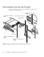
Page 28: ...f rack installation and components and corresponds to the steps that follow Figure 2 1 Overview of Standard 19 Inch EIA Rackmounting Components 10 32 x 5 8 in Truss screws Threaded PEMs 4 Rear bracket connected to rack 10 32 x 5 8 in Truss screws Side bracket Step 6 Step 5 Step 8 Step 9 8 32 x 3 16 in flathead screws 8 32 x 1 4 in flathead screws ...

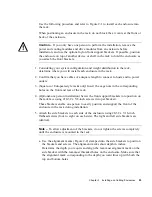
Page 29: ...ks only Insert the cage nuts in the corresponding holes on the front and rear of the rack 4 Optional one person installation Screw the front support brackets into position on the rack face using 10 32 x 5 8 inch screws two per bracket These brackets enable one person to easily position and support the front of the enclosure in the rack during installation 5 Attach the side brackets to each side of...

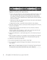
Page 30: ...the rack using 10 32 x 5 8 inch screws two per bracket 7 Lift the enclosure and slide the side brackets into the rear brackets which are attached to the rear posts Adjust the depth of the side brackets so that the slots nearest the ends of the side brackets align with the four PEM nuts in the rear brackets 8 Attach each side bracket to a rear bracket using 8 32 x 1 4 inch screws four per bracket 9...

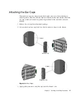
Page 31: ... been installed in the rack cabinet attach the ear caps which are located in a plastic bag included in the controller enclosure package 1 Remove the ear caps from the plastic package 2 As you attach each ear cap hold it so that its indent is closest to the chassis Figure 2 3 Ear Caps 3 Apply gentle pressure to snap the caps onto the chassis ears Right ear cap Left ear cap Indent Indent ...

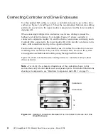
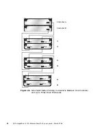
Page 32: ...onnected to the lower module B of the last drive enclosure in the chain with connections moving in the opposite direction Fault tolerant cabling is recommended because it enables the controllers to access remaining drive enclosures if any one drive enclosure fails However the system also supports non fault tolerant cabling using the supplied SAS cables Figure 2 6 shows non fault tolerant cabling b...

Page 33: ...and Cabling Enclosures 33 Figure 2 5 Fault Tolerant Cabling Connections Between One Controller Enclosure and Up to Three Drive Enclosures In Out In Out In Out In Out Controller B Controller A 1A 1B 2A 2B 3A 3B In Out In Out ...

Page 34: ...ular Smart Array user guide March 2008 Figure 2 6 Non Fault Tolerant Cabling Connections Between One Controller and Up to Three Drive Enclosures In Out In Out In Out In Out In Out In Out Controller B Controller A 1A 1B 2A 2B 3A 3B ...

Page 35: ...switches are off 2 Using the AC power cords for each enclosure connect one power and cooling module to one power source in the rack and the other power and cooling module to a separate power source in the rack 3 Connect the primary power cords from the rack to separate external power sources Power on the system as described in the topic that follows ...

Page 36: ...e controller enclosure Depending on your configuration it can take several minutes for the system to power up While enclosures power up their LEDs blink After the LEDs stop blinking if no LEDs on the front and back of the enclosure are amber the power on sequence is complete and no faults have been detected For a description of LED behavior and status see Hardware Components and LEDs on page 13 2 ...

Page 37: ...ss for the two IP addresses assigned to an HP StorageWorks MSA2000 Family storage device 2 Use a network management utility to discover HP StorageWorks MSA2000 Family storage devices on the local LAN through SNMP 3 Use a ping broadcast to try to identify the device through the host s ARP table Data Host Ethernet Port From your network administrator obtain an IP address for each data host Ethernet ...

Page 38: ...th the physical cabling order This is because the controller might have been previously attached to some of the same enclosures and it attempts to preserve the previous enclosure IDs if possible To correct this condition make sure that both controllers are up and perform a rescan using SMU or the CLI This will reorder the enclosures but can take up to two minutes for the enclosure IDs to be correc...

Page 39: ...A QuickSpecs QuickSpecs can be found from your HP MSA products page at http www hp com go msa Select MSA SAN Arrays and then select your product The link for QuickSpecs will be on the right For systems using NIC hardware you must install and configure the Microsoft iSCSI Software Initiator For more information see Installing the Microsoft iSCSI Software Initiator on page 40 Depending on your syste...

Page 40: ...nnectivity on Ethernet host ports The software initiator must be installed in addition to standard Microsoft Windows network and HBA drivers 1 Locate and download the Microsoft iSCSI Software Initiator Version 2 06 for your host system found at http www microsoft com downloads 2 Install the software initiator as directed on the download site If the operating system on your data host supports MPIO ...

Page 41: ...package Connecting Data Hosts to Controller Enclosures This section explains how to connect the controller enclosure to data hosts through Ethernet switches The controller enclosure has four host connections two per controller Connect Ethernet cables from controller hosts ports to switch ports and from switch ports to data hosts as shown in the following figure To maintain redundancy connect each ...

Page 42: ...ability dual controller connection through two switches to two dual port data hosts in which each data host has two Ethernet ports with each port connected to a different switch Figure 3 1 High Availability Connection Through Two Switches to Two Dual Port Data Hosts Switch A Switch B Controller B Controller A ...

Page 43: ...confuse Ethernet management ports with Ethernet host ports also located on the rear panel of the controller enclosure For a description of controller enclosure ports see Hardware Components and LEDs on page 13 2 Connect the other end of each Ethernet cable to a network that your management host can access preferably on the same subnet Next Steps After you have connected the management host and dat...

Page 44: ...44 HP StorageWorks 2012i Modular Smart Array user guide March 2008 ...

Page 45: ...9 Updating Firmware on page 50 Setting the Date and Time on page 50 Configuring Controller Enclosure Host Ports on page 52 Configuring Data Host Ethernet Ports on page 52 Configuring the Microsoft iSCSI Software Initiator on page 53 Editing Registry Values for Ethernet Adapters on page 55 Creating Virtual Disks on page 58 Mapping a Data Host to a Volume on page 59 Testing the Configuration on page...

Page 46: ...the default IP addresses are not compatible with your network you must set an IP address for each management port using the command line interface CLI embedded in each controller module The CLI enables you to access the system using RS 232 communication and terminal emulation software Use the CLI commands described in the steps below to set the IP address for the Ethernet management port on each c...

Page 47: ... a terminal emulator such as HyperTerminal or VT 100 using the display settings in Table 4 1 and the connection settings in Table 4 2 Table 4 1 Terminal Emulator Display Settings Parameter Value Terminal Emulation Mode VT 100 or ANSI for color support Font Terminal Translations None Columns 80 Table 4 2 Terminal Emulator Connection Settings Parameter Value Connector COM1 typically Baud rate bits s...

Page 48: ...address of the subnet router a b specifies the controller whose network parameters you are setting For example 6 Type the following command to verify the new IP addresses Network parameters including the IP address subnet mask and gateway address are displayed for each controller 7 Disconnect from the CLI and exit the emulator set network parameters ip address netmask netmask gateway gateway contr...

Page 49: ... for SMU Before using SMU to perform remaining steps ensure that your web browser is properly configured according to the following guidelines Use one of the following browsers Microsoft Internet Explorer 5 5 or later Mozilla Firefox 1 0 7 or later Because SMU uses popup windows to indicate the progress of user requested tasks disable any browser features or tools that block popup windows For opti...

Page 50: ...fy that the controllers and drive enclosures have the latest firmware SMU enables you to view the software hardware and other version information for each controller and the enclosures To view controller version information select Monitor Status Advanced Settings Controller Versions To view drive enclosure information select Manage Update Software Enclosure Firmware Show Enclosures For software an...

Page 51: ...system date and time 1 Select Manage General Config Set Date Time 2 In the Set System Date panel select the current month day and year 3 In the Set System Time panel type time values using a 24 hour clock where hour 8 represents 8 a m and hour 20 represents 8 p m and select the proper time zone 4 Click Change Date Time To obtain the date and time from an NTP server 1 Select Manage General Config S...

Page 52: ...ata host Ethernet port that will be used for iSCSI connectivity Each Ethernet port on a data host should be assigned an IP address on a different subnet To configure data host Ethernet ports for iSCSI connectivity so that hosts can communicate with the storage system complete the following steps 1 On the host system click Start Control Panel Network Connections 2 Select and rename each Ethernet po...

Page 53: ...arget from the data host to initiate connectivity between the data host and the storage system Note Before completing the steps that follow you must connect storage system enclosures as described in Installing and Cabling Enclosures on page 25 You must also install all software and drivers required on data hosts see Host System Requirements on page 39 and connect hosts to the storage system as des...

Page 54: ...ft iSCSI Initiator from the drop down menu ii At the Source IP field select the IP address for the local data Ethernet port that is on the same subnet as the first target portal iSCSI host port to which you want the host to connect iii At the Target Portal field select the IP address for the iSCSI host port on the target controller module to which you are connecting iv Repeat the log on procedure ...

Page 55: ...ectly If not correct IP address settings d Log on again for each target using the instructions in this section starting at Step 2 The data host can now communicate with the controllers through iSCSI Ethernet host ports Editing Registry Values for Ethernet Adapters Note This section applies only to Microsoft Windows hosts that use Ethernet adapters NIC hardware for iSCSI connectivity For the iSCSI ...

Page 56: ...ControlSet Services Tcpip Parameters Interfaces The interfaces will be listed below the key using automatically generated Globally Unique Identifiers GUIDs Example 064A622F 850B 4C97 96B3 0F0E99162E56 3 Select and perform the following steps for each GUID a Check the IPAddress or DhcpIPAddress parameters to determine whether the interface is used for iSCSI traffic If not skip to the next GUID b If...

Page 57: ...select the following registry subkey HKEY_LOCAL_MACHINE SYSTEM CurrentControlSet Control Class 4D36E97B E325 11CE BFC1 08002BE10318 Instances will be listed below the key using automatically generated GUIDs Example 0000 0001 2 Select and perform the following steps for each instance ID a Check to see whether the DriverDesc parameter is set to Microsoft iSCSI Initiator If not skip to the next inter...

Page 58: ...osts To create both virtual disks 1 In SMU select Manage Virtual Disk Config Create A Vdisk 2 Select Manual Virtual Disk Creation Detail based 3 Type a name for the virtual disk The name is case sensitive and can include 17 characters Allowed characters include letters numbers hyphens underscores and spaces 4 Select RAID 5 Parity RAID Parity Distributed 5 Click Create New Virtual Disk 6 Select fiv...

Page 59: ...are set to None 2 In the Assign Host Access Privileges panel a Select the host port IQN value that you identified before beginning b Type the LUN that you identified Notice that the mapped host will have read write access through all controller host ports c Click Map It Testing the Configuration To determine that your system is ready for use test the configuration as follows 1 In SMU select Monito...

Page 60: ...shed using it other manage users cannot log in to the same controller module and your IP address stays logged in for 30 minutes the default auto logout timeout setting To log out of SMU 1 Click Log Off at the bottom of the menu The Log Off page is displayed 2 Click Log Off Next Steps You have completed the initial configuration tasks covered in this guide For additional information on configuring ...

Page 61: ... switches at the back of each drive enclosure to the Off O position Powering On the System Power on any drive enclosures before powering on the controller enclosure This ensures that the disks in the drive enclosures have enough time to completely spin up before being scanned by the RAID controllers in the controller enclosure Depending on your configuration it can take several minutes for the sys...

Page 62: ...i Modular Smart Array user guide March 2008 2 Press the power switches at the back of the controller enclosure to the On position If the enclosure s power on sequence succeeds as described in Step 1 the system is ready to use ...

Page 63: ...e installed in a residential environment i e personal computers The FCC requires devices in both classes to bear a label indicating the interference potential of the device as well as additional operating instructions for the user The rating label on the device shows which class A or B the equipment falls into Class B devices have an FCC logo or FCC ID on the label Class A devices do not have an F...

Page 64: ...ause harmful interference to radio or television reception which can be determined by turning the equipment off and on the user is encouraged to try to correct the interference by one or more of the following measures Reorient or relocate the receiving antenna Increase the separation between the equipment and receiver Connect the equipment into an outlet on a circuit that is different from that to...

Page 65: ...n your product has been assigned a unique Regulatory Model Number The RMN can be found on the product nameplate label along with all required approval markings and information When requesting compliance information for this product always refer to this RMN The Regulatory Model Number should not be confused with the marketing name or model number of the product Regulatory Compliance Label Location ...

Page 66: ...s port In the USA the FO transceiver is certified as a Class 1 laser product conforming to the requirements contained in the Department of Health and Human Services DHHS regulation 21 CFR Subchapter J A label on the plastic FO transceiver housing indicates the certification Outside the USA the FO transceiver is certified as a Class 1 laser product conforming to the requirements contained in IEC 82...

Page 67: ...t sur le matériel brouilleur du Canada European Union Notice Products bearing the CE marking comply with the EMC Directive 89 336 EEC and the Low Voltage Directive 73 23 EEC issued by the Commission of the European Community and if this product has telecommunication functionality the R TTE Directive 1999 5 EC Compliance with these directives implies conformity to the following European Norms in pa...

Page 68: ...68 HP StorageWorks 2012i Modular Smart Array user guide March 2008 Also approved under UL 60950 CSA C22 2 No 60950 00 Safety of Information Technology Equipment BSMI Notice Japanese Notice ...

Page 69: ...gnated for this product For more information about battery replacement or proper disposal contact an HP authorized reseller or HP authorized service provider Warning Your computer contains an internal lithium manganese dioxide a vanadium pentoxide or an alkaline battery pack There is risk of fire and burns if the battery pack is not properly handled To reduce the risk of personal injury Do not att...

Page 70: ... 00 mm2 or 18 AWG and the length of the cord must be between 1 8 m 6 ft and 3 6 m 12 ft If you have questions about the type of power cord to use contact an HP authorized service provider Note Route power cords so that they will not be walked on and cannot be pinched by items placed upon or against them Pay particular attention to the plug electrical outlet and the point where the cords exit from ...

Page 71: ...ontainers Avoid touching pins leads or circuitry Always be properly grounded when touching a static sensitive component or assembly see Grounding Methods on page 71 Grounding Methods There are several methods for grounding Use one or more of the following methods when handling or installing electrostatic sensitive parts Use a wrist strap connected by a ground cord to a grounded workstation or comp...

Page 72: ...et ikke må bortskaffes med andet almindeligt husholdningsaffald I stedet er det dit ansvar at bortskaffe kasseret udstyr ved at aflevere det på den kommunale genbrugsstation der forestår genvinding af kasseret elektrisk og elektronisk udstyr Den centrale modtagelse og genvinding af kasseret udstyr i forbindelse med bortskaffelsen bidrager til bevarelse af naturlige ressourcer og sikrer at udstyret...

Page 73: ... equipment for recycling please contact your local city office your household waste disposal service or the shop where you purchased the product Verwijdering van afgedankte apparatuur door privé gebruikers in de Europese Unie Dit symbool op het product of de verpakking geeft aan dat dit product niet mag worden gedeponeerd bij het normale huishoudelijke afval U bent zelf verantwoordelijk voor het i...

Page 74: ...Lisateabe saamiseks selle kohta kuhu oma seadmete jäätmed ringlussevõtmiseks viia võtke palun ühendust oma kohaliku linnakantselei majapidamisjäätmete kõrvaldamise teenistuse või kauplusega kust Te toote ostsite Laitteiden hävittäminen kotitalouksissa Euroopan unionin alueella Jos tuotteessa tai sen pakkauksessa on tämä merkki tuotetta ei saa hävittää kotitalousjätteiden mukana Tällöin hävitettävä...

Page 75: ...mations sur les centres de collecte et de recyclage des appareils mis au rebut veuillez contacter les autorités locales de votre région l es services de collecte des ordures ménagères ou le magasin dans lequel vous avez acheté ce produit Entsorgung von Altgeräten aus privaten Haushalten in der EU Das Symbol auf dem Produkt oder seiner Verpackung weist darauf hin dass das Produkt nicht über den nor...

Page 76: ...vásárló a hulladékká vált készüléket köteles a kijelölt gy jt helyre szállítani az elektromos és elektronikai készülékek újrahasznosítása céljából A hulladékká vált készülékek selejtezéskori begy jtése és újrahasznosítása hozzájárul a természeti er források meg rzéséhez valamint biztosítja a selejtezett termékek környezetre és emberi egészségre nézve biztonságos feldolgozását A begy jtés pontos he...

Page 77: ...ontattare l ente locale per lo smaltimento dei rifiuti oppure il negozio presso il quale è stato acquistato il prodotto Nolietotu iek rtu izn cin šanas noteikumi lietot jiem Eiropas Savien bas priv taj s m jsaimniec b s Š ds simbols uz izstr d juma vai uz t iesai ojuma nor da ka šo izstr d jumu nedr kst izmest kop ar citiem sadz ves atkritumiem J s atbildat par to lai nolietot s iek rtas tiktu nod...

Page 78: ...etot s iek rtas var izmest otrreiz jai p rstr dei j v ršas savas dz ves vietas pašvald b sadz ves atkritumu sav kšanas dienest vai veikal kur izstr d jums tika nopirkts Pozbywanie si zu ytego sprz tu przez u ytkowników w prywatnych gospodarstwach domowych w Unii Europejskiej Ten symbol na produkcie lub jego opakowaniu oznacza e produktu nie wolno wyrzuca do zwykłych pojemników na mieci Obowi zkiem...

Page 79: ...ar o material usado lixo elétrico encaminhando o para um ponto de coleta para reciclagem A coleta e a reciclagem seletivas desse tipo de lixo ajudarão a conservar as reservas naturais sendo assim a reciclagem será feita de uma forma segura protegendo o ambiente e a saúde das pessoas Para obter mais informações sobre locais que reciclam esse tipo de material entre em contato com o escritório da HP ...

Page 80: ...epositándolos en un punto limpio para el reciclado de residuos eléctricos y electrónicos La recogida y el reciclado selectivos de los residuos de aparatos eléctricos en el momento de su eliminación contribuirá a conservar los recursos naturales y a garantizar el reciclado de estos residuos de forma que se proteja el medio ambiente y la salud Para obtener más información sobre los puntos de recogid...

Page 81: ...t bortskaffa avfallet genom att överlämna det till ett uppsamlingsställe avsett för återvinning av avfall från elektriska och elektroniska produkter Separat insamling och återvinning av avfallet hjälper till att spara på våra naturresurser och gör att avfallet återvinns på ett sätt som skyddar människors hälsa och miljön Kontakta ditt lokala kommunkontor din närmsta återvinningsstation för hushåll...

Page 82: ...82 HP StorageWorks 2012i Modular Smart Array user guide March 2008 ...

Page 83: ...ecting AC power 35 controller and drive enclosures 32 controller enclosures to data hosts 41 serial cable to set IP address 46 to remote management hosts 43 using reverse cabling 32 controller enclosures components 13 configuring host ports 52 connecting to data hosts 41 connecting to multiple drive enclosures 32 connecting to remote management hosts 43 controller modules LEDs cache status 18 Ethe...

Page 84: ...ort status 22 Unit Locator 21 location 20 ports SAS In 20 SAS Out 20 service 20 F failover 11 fault tolerance 32 33 FCC Federal Communications Commission Class A Equipment compliance notice 63 Class B Equipment compliance notice 64 declaration of conformity 64 modifications 65 notice 63 Federal Communications Commission See FCC floor mats dissipating 71 G ground strap specifications 71 grounding m...

Page 85: ...ing storage systems using SMU 12 using the CLI 12 mapping data hosts to volumes 59 P parts proper handling 71 storing 71 transporting 71 ports expansion 16 host 16 SAS In 20 SAS Out 20 service 20 power connecting AC 35 switches 16 power and cooling modules LEDs AC Power Good 17 21 DC Voltage Fan Fault Service Required 17 21 power switches 16 20 power cord compliance notice 70 current rating 70 rep...

Page 86: ...orage website 10 straps ground boot 71 heel 71 toe 71 Subscriber s choice website 10 Subscriber s choice HP 10 switch attach configurations 41 T Taiwan EPA battery recycling and disposal 70 telephone numbers FCC questions 64 terminal emulator connection settings 47 display settings 47 toe straps using 71 tools required for installation 25 tools conductive type 71 U UID LED 14 Unit identification U...

Reviews: