88
Configuration
Disk Addressing
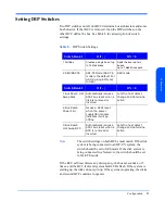
Each disk in the StorageWorks Disk System 2300 occupies a separate address
(SCSI ID) on the SCSI bus. Disk addresses range from 0 to 6 and 8 to 14 in full-
bus mode (DIP switch 1 set to “|”). In split bus mode (DIP switch 1 set to “0”),
the left BCC (viewing the disk system from the rear) is on the high numbered
bank (with disk slots 8, 9, 10, 11,12, 13, and 14) and the right BCC is on the low
numbered bank (with disk slots 0, 1, 2, 3,4, 5, and 6) of disk slots. Address 7 is
reserved for host bust adapter(s). The BCCs take address 15.
Table 10 shows all target SCSI IDs for full bus and split bus modes.
Table 10.
Disk and BCC SCSI Addresses for Full and Split Bus Modes
Physical
Disk Slot
SCSI ID
Full Bus
Split Bus
(Right BCC)
Split Bus
(Left BCC)
1
0
0
2
1
1
3
2
2
4
3
3
5
4
4
6
5
5
7
6
6
8
8
8
9
9
9
10
10
10
11
11
11
12
12
12
13
13
13
14
14
14
Right BCC
15
15
Left BCC B
See Note
15
Summary of Contents for StorageWorks 2300 - Disk System
Page 1: ...hp StorageWorks disk system 2300 Edition E0902 user s guide ...
Page 10: ...10 ...
Page 14: ...14 Product Description ...
Page 35: ...Installation 35 Installation 2 ...
Page 40: ...40 Installation ...
Page 41: ...Installation 41 Installation ...
Page 48: ...48 Installation ...
Page 58: ...58 Installation ...
Page 59: ...Installation 59 Installation 4 Install clipnuts as shown in Figure 28 ...
Page 76: ...76 Installation ...
Page 77: ...Installation 77 Installation ...
Page 83: ...Configuration 83 Configuration 3 ...
Page 86: ...86 Configuration ...
Page 94: ...94 Configuration ...
Page 95: ...Troubleshooting 95 Troubleshooting 4 ...
Page 108: ...108 Removal and Replacement ...
Page 132: ......
Page 134: ......
Page 140: ......
Page 150: ...150 Reference E VCCI Statement Japan Harmonics Conformance Japan F BCIQ EMC Statement Taiwan ...
Page 151: ...Reference 151 Reference G Declaration of Conformity ...
Page 158: ...158 ...


