Whenever the EMU detects a condition that could affect operation, it performs the following operations:
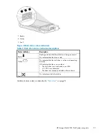
•
Generates an audible alarm
•
Displays status in visual indicators
•
Generates an error condition report
•
Reports the condition to the HP-UX application software
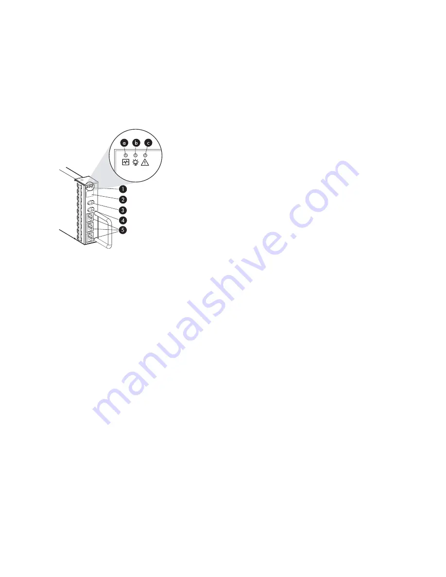
Controls and displays
Figure 3
identi
fi
es the EMU displays, controls, and connectors.
25236a
Figure 3 EMU controls and displays
1.
Status indicators:
a.
EMU heartbeat—Flashing green signi
fi
es an operational EMU
b.
DS2500 power—Solid green signi
fi
es that the +5 VDC and +12 VDC signals are within
an acceptable range
c.
DS2500 fault—Solid amber indicates that an enclosure error condition exists (normally off)
2.
Alphanumeric display—A two-character display of the enclosure functions and status (typically
displays the enclosure ID).
3.
Function select push button and back light—Enables you to specify what information appears in
the alphanumeric display. Pressing and releasing, or tapping the function select button allows
you to sequence through the different sublevels of a display group. The back light is on when
an error condition exists.
4.
Display group select push button and back light—Enables you to view display groups and
control the audible alarm. The back light is on when the audible alarm is muted or disabled.
5.
Communication ports—Unused in a JBOD environment
I/O modules (E-PBC)
Two I/O modules provide an interface between the disks and the host system. The I/O modules are used
to route data to and from the disks in a dual-loop con
fi
guration to eliminate a single point of failure.
Each disk drive is connected to both I/O module A and I/O module B (
Figure 4
-3). Each I/O module is
connected to an independent, external FC loop. I/O module A connects to loop A, and I/O module B
connects to loop B (see
Figure 1
on page 14).
18
Components
Summary of Contents for StorageWorks 2500
Page 1: ...HP StorageWorks 2500 Disk System user guide Part number 5697 6800 Second edition June 2007 ...
Page 8: ...8 ...
Page 12: ...12 About this guide ...
Page 44: ...44 Using the EMU ...
Page 54: ...54 Troubleshooting ...
Page 64: ...Figure 35 Replacing a disk drive 64 Customer self repair ...
Page 68: ...68 Specifications ...
Page 78: ...78 Regulatory notices ...


