background image

podrobnejše informacije o tem, kam lahko odpeljete odsluženo opremo na recikliranje, se obrnite na

pristojni organ, komunalno službo ali trgovino, kjer ste izdelek kupili.

Spanish notice

Eliminación de residuos de equipos eléctricos y electrónicos por parte de usuarios particulares en la

Unión Europea

Este símbolo en el producto o en su envase indica que no debe eliminarse junto con los

desperdicios generales de la casa. Es responsabilidad del usuario eliminar los residuos de este tipo

depositándolos en un "punto limpio" para el reciclado de residuos eléctricos y electrónicos. La recogida

y el reciclado selectivos de los residuos de aparatos eléctricos en el momento de su eliminación

contribuirá a conservar los recursos naturales y a garantizar el reciclado de estos residuos de forma que

se proteja el medio ambiente y la salud. Para obtener más información sobre los puntos de recogida

de residuos eléctricos y electrónicos para reciclado, póngase en contacto con su ayuntamiento, con el

servicio de eliminación de residuos domésticos o con el establecimiento en el que adquirió el producto.

Swedish notice

Bortskaffande av avfallsprodukter från användare i privathushåll inom Europeiska Unionen

Om den här symbolen visas på produkten eller förpackningen betyder det att produkten inte får

slängas på samma ställe som hushållssopor. I stället är det ditt ansvar att bortskaffa avfallet genom att

överlämna det till ett uppsamlingsställe avsett för återvinning av avfall från elektriska och elektroniska

produkter. Separat insamling och återvinning av avfallet hjälper till att spara på våra naturresurser och

gör att avfallet återvinns på ett sätt som skyddar människors hälsa och miljön. Kontakta ditt lokala

kommunkontor, din närmsta återvinningsstation för hushållsavfall eller affären där du köpte produkten för

att få mer information om var du kan lämna ditt avfall för återvinning.

Germany noise declaration

Schalldruckpegel Lp = 70 dB(A)
Am Arbeitsplatz (operator position)
Normaler Betrieb (normal operation)
Nach ISO 7779:1999 (Typprüfung)

Japanese notice

76

Regulatory notices

Summary of Contents for StorageWorks 2500

Page 1: ...HP StorageWorks 2500 Disk System user guide Part number 5697 6800 Second edition June 2007 ...

Page 2: ...bject to change without notice The only warranties for HP products and services are set forth in the express warranty statements accompanying such products and services Nothing herein should be construed as constituting an additional warranty HP shall not be liable for technical or editorial errors or omissions contained herein ...

Page 3: ...s 16 2 Components 17 List of parts 17 EMU 17 EMU functions 17 Controls and displays 18 I O modules E PBC 18 Power supply and blower assembly 20 Features 21 Power supply and blower status indicator 21 Fibre Channel disks 21 Disk drive status indicators 22 Drive blanks 24 Cables and cabling 24 Transceivers 24 3 Installation 25 Preparing to install a DS2500 25 Unpacking the shipping carton 25 Install...

Page 4: ...ty levels 48 Error condition reports 48 Status indicators 48 Audible error indicators 50 Visual error indicators 50 I O module and transceivers 50 Disk drives 51 Catastrophic errors 52 EMU temperature warning and shutdown operation 53 6 Customer self repair 55 Customer self repair 55 Parts only warranty service 56 Best practices for replacing hardware components 56 Verifying component failure 57 P...

Page 5: ...ice 73 Greek notice 73 Hungarian notice 74 Italian notice 74 Latvian notice 74 Lithuanian notice 74 Polish notice 75 Portuguese notice 75 Slovakian notice 75 Slovenian notice 75 Spanish notice 76 Swedish notice 76 Germany noise declaration 76 Japanese notice 76 Harmonics conformance Japan 77 Taiwanese notice 77 Japanese power cord notice 77 Country specific certifications 77 C EMU generated error ...

Page 6: ... 15 Drive blank 30 16 Removing a power supply blower assembly 30 17 Removing the EMU 31 18 Removing an I O module 31 19 Enclosure thumbscrews 32 20 Installing a disk drive 32 21 EMU alphanumeric display and controls 33 22 Enclosure operational status indicators 33 23 FC AL loops 34 24 Drive blank 36 25 Installing a disk drive 37 26 LEDs in the operational state 50 27 I O module status LEDs 51 28 D...

Page 7: ...erating specifications 65 16 Environmental shipping or short term storage specifications 66 17 DS2500 AC input line voltages 66 18 AC input current and wattage 67 19 Output voltage and current specifications 67 20 Power specifications 67 21 Element type 79 22 Disk drive error conditions 80 23 Power supply error conditions 81 24 Blower error conditions 82 25 Temperature sensor element numbers 82 26...

Page 8: ...8 ...

Page 9: ...ind these documents on the HP web site http www hp com support manuals In the Storage section click Disk Storage Systems and then select your product Document conventions and symbols Table 1 Document conventions Convention Element Blue text Table 1 Cross reference links and e mail addresses Blue underlined text http www hp com Web site addresses Bold text Keys that are pressed Text typed into a GU...

Page 10: ...e full weight of the rack rests on the leveling jacks Install stabilizing feet on the rack In multiple rack installations fasten racks together securely Extend only one rack component at a time Racks can become unstable if more than one component is extended HP technical support Telephone numbers for worldwide technical support are listed on the HP support web site http www hp com support Collect ...

Page 11: ...e http www hp com go e updates Subscribing to this service provides you with e mail updates on the latest product enhancements newest driver versions and firmware documentation updates as well as instant access to numerous other product resources After subscribing locate your products by selecting Business support and then Storage under Product Category Other HP web sites For additional informatio...

Page 12: ...12 About this guide ...

Page 13: ...h the affected file systems must be taken offline Environmental services sensors that monitor the disk enclosure and provide real time error reporting High availability to minimize unplanned downtime Customer replaceable components Each DS2500 is connected to Host Bus Adapters HBAs through two independent Fibre Channel Arbitrated Loop FC AL buses also known as loops to provide no single point of f...

Page 14: ...t For simplicity a drive is referred to by its bay number Enclosure status indicators located in the lower corner to the right of bay 14 DS2500 rear view The rear of the DS2500 holds the following components An Environmental Monitoring Unit EMU that provides protection against catastrophic failures It monitors records and reports disk enclosure status conditions to the operating system software Re...

Page 15: ...port overall DS2500 status Indicators on the top rear of the EMU report overall DS2500 status duplicates of the indicators on the front of the enclosure A status LED on each power supply blower assembly verifies proper operation of the assembly Status LEDs on each I O module indicate the detection of transceiver signals and power An audible alarm alerts you to an error condition Specific LED infor...

Page 16: ...list of supported HBAs see the DS2500 QuickSpecs on the HP storage web site http www hp com support manuals In the Storage section click Disk Storage Systems and then select your product In the Resources for my selected product section select See more and then HP product bulletins QuickSpecs Disk drives The DS2500 supports high speed FC disk drives For a list of supported disk drives see the DS250...

Page 17: ...2 I O modules 2 power supplies 2 blowers Small Form factor Pluggable SFP transceivers Fiber optic cables EMU The EMU monitors and records disk enclosure status information EMU functions The primary functions of the EMU include Display or change the enclosure ID En Display or change the enclosure loop ID Monitor enclosure operation Detect report record and display enclosure error status conditions ...

Page 18: ...ct push button and back light Enables you to specify what information appears in the alphanumeric display Pressing and releasing or tapping the function select button allows you to sequence through the different sublevels of a display group The back light is on when an error condition exists 4 Display group select push button and back light Enables you to view display groups and control the audibl...

Page 19: ...al Each I O module has two ports that can transmit and receive data for bidirectional operation Port use and connections are configuration dependent see Cables and cabling on page 24 Each port is identified with a transceiver element number and its status is displayed on an LED Figure 5 Port 1 is the bottom loop port and port 2 is the top loop port Port 2 LED On indicates that a signal was detecte...

Page 20: ...are not interchangeable Physical differences between the modules require you to install I O module A at the right side of the enclosure behind drive bay 1 I O module B at the left side of the enclosure next to the EMU Power supply and blower assembly Figure 6 shows the power supply and blower assembly components 20 Components ...

Page 21: ...eptable level of any of these elements the status indicator turns off and an error is reported to the EMU The EMU uses the temperature sensor signal to adjust the speed of the blowers If one blower fails or spins at a reduced speed the speed of the other blower increases to provide adequate air flow Power supply and blower status indicator A green LED on the blower Figure 6 2 indicates the operati...

Page 22: ...ive blank in each bay To avoid overheating never remove more than one disk or drive blank from an operating enclosure at the same time Disk drive status indicators Three status indicators Ready Online and Fault show the drive operational status Figure 8 Table 2 provides a description of each status indicator 22 Components ...

Page 23: ...icates that the drive is idle Online On indicates that the disk drive is online and operating normally Off indicates that there is a problem This disk drive is not connected to an HBA 5 1 VDC is not detected The drive is not properly installed in the enclosure Fault On indicates a disk drive failure Additional status codes are described in Disk drives on page 51 HP StorageWorks 2500 Disk System us...

Page 24: ...0 micron μm diameter multimode fibre cables The input port connects to an HBA or the previous enclosure in the loop and the output port connects to the next enclosure or an HBA on the loop Transceivers The DS2500 uses a short wavelength fiber optic transceiver called a Small Form factor pluggable SFP that does not pose a threat to the human eye SFPs are installed in the I O module ports 24 Compone...

Page 25: ...NING A DS2500 with all components installed weighs more than 29 5 kg 65 lb and requires a minimum of two people to move To safely and easily install the DS2500 using antistatic protection remove the drive blanks power supply blower assemblies EMU and I O modules This reduces the weight of the DS2500 to approximately 1 1 0 kg 24 lb Even though a single person can lift this weight the DS2500 is diff...

Page 26: ...e loop ID Li page 35 7 Verifying the installation page 36 NOTE HP recommends that you install the heaviest components low in the rack to ensure rack stability Installing the snap in rails 1 2 CXO8193A 3 1 Left rack rail 2 Right rack rail 3 Pins for round hole rack conversion 8 Figure 10 Contents of snap in rail mounting kit You can identify the left and right rack rails by the markings L and R sta...

Page 27: ...ewdriver to remove the standard pins from the front and back ends of a rail 4 Install four round hole pins into the rail Figure 1 1 5 Repeat steps 3 and 4 on the other rail CXO8194A Figure 1 1 Converting the rails for round hole racks Installing the rails For each rail 1 Determine where the rails will be mounted and use the rack template to mark the U holes through which the pins will extend 2 Ins...

Page 28: ...les marked in Step 1 and the scissor type locking latch is fully engaged Figure 13 CXO8196A Figure 13 Inserting the rail into the rear rack column 4 Locate the shipping bracket on the rail Figure 14 5 Use a No 2 Phillips screwdriver to loosen the shipping bracket and slide the bracket toward the back of the rack 6 Install the other rail by repeating Step 1 through Step 5 28 Installation ...

Page 29: ...onents installed weighs more than 29 5 kg 65 lb and requires a minimum of two people to move To safely and easily install the DS2500 remove the components as described in this section This reduces the DS2500 weight to approximately 1 1 0 kg 24 lb CAUTION Parts can be damaged by electrostatic discharge Use proper antistatic protection as described in the documentation that shipped with your system ...

Page 30: ...sembly out of the enclosure 2 Place the power supply blower assembly on an antistatic work space 1 Power cord lock 2 Mounting latch 3 Blower Figure 16 Removing a power supply blower assembly Removing the EMU To remove the EMU 1 Grasp the EMU handle Figure 17 1 and taking care not to tilt it pull the EMU module straight out of the enclosure Figure 17 2 2 Place the EMU on an antistatic surface 30 In...

Page 31: ... surface Figure 18 Removing an I O module Installing the DS2500 in the rack WARNING A DS2500 without components installed weighs approximately 1 1 0 kg 24 lb Even though a single person can lift this weight the DS2500 is difficult to install because of its physical size Therefore HP recommends that a minimum of two people install an empty DS2500 in a rack To install a DS2500 1 From the front of th...

Page 32: ...se lever until the ejector button engages and the disk drive engages in the backplane Figure 20 2 Figure 20 Installing a disk drive 5 Install disk blanks in all bays that do not contain a disk drive 6 Connect a power cord to each power supply and engage the cord locks 7 Plug the power cords into separate AC power receptacles TIP Using separate power receptacles provides no single point of failure ...

Page 33: ...necting the cables Figure 23 shows a FC AL configuration with the maximum allowed DS2500s To connect fibre optic cables on a direct connect model 1 Remove the dust covers from the I O module ports 2 Insert an SFP in each I O port 3 Attach one end of an FC cable to I O module A port 2 SFP and the other end of the cable to either The SFP in port 1 of I O module A on the preceding enclosure if you ar...

Page 34: ...ugh Step 5 7 Verify the FC connections by observing that the port status indicators are on and steady 8 Verify that the EMU heartbeat indicator is flashing 9 Verify that the disk drives are online by observing their online LEDs 25176a 10 1 3 2 4 1 Loop B Connects to HBA 3 Loop A Connects to HBA 2 Loop B Connects to HBA 4 Loop A Connects to HBA Figure 23 FC AL loops Setting the enclosure ID En You ...

Page 35: ...he loop ID 1 Tap the bottom push button until the alphanumeric display is Li 2 Tap the top push button The loop ID appears in the alphanumeric display 3 If the loop ID is set to the correct value based on the enclosure ID skip to Step 6 otherwise continue with Step 4 4 Press and hold the top push button until the alphanumeric display blinks 5 Tap the top push button until the loop ID that correspo...

Page 36: ...which the disk is installed HP UX stores the loop ID and WWN of each disk and uses them to authenticate the disk Verifying the installation Use IOSCAN to verify that the S W state of the disks is CLAIMED Adding drives to an existing DS2500 You can add disk drives to an existing DS2500 without interrupting enclosure operation CAUTION Parts can be damaged by electrostatic discharge Use proper antist...

Page 37: ... system complete the procedure for each of the four disks one at a time and then repeat it for another set of four until all drives have been added CAUTION To ensure proper airflow remove only one drive blank at a time from an operating enclosure NOTE This procedure applies to the physical installation of disks into DS2500 bays 1 Insert up to four disk drives into their respective DS2500 bays as d...

Page 38: ... the drives you inserted in Step 1 have displayed a solid green ready indicator for at least 10 seconds you can repeat this procedure with another set of up to four drives 4 When all drives have been inserted verify the addition of the new drives see Verifying the installation on page 36 38 Installation ...

Page 39: ... The bottom push button lights when the audible alarm is muted or disabled Display groups By default the enclosure ID En appears in the alphanumeric display When you press and release the bottom push button the display cycles among the display groups listed in Table 4 A flashing alphanumeric display indicates that you can edit the contents of a display group Table 4 EMU display groups Display grou...

Page 40: ...the updated enclosure ID see Loop ID Li Loop ID Li The loop ID is a hexadecimal number that you must set to correspond with the enclosure ID See Table 5 for the enclosure ID and loop ID pairs To set the loop ID 1 Tap the bottom push button until the alphanumeric display is Li 2 Tap the top push button The loop ID appears in the alphanumeric display 3 If the loop ID is set to the correct value base...

Page 41: ...r condition is present regardless of the audible alarm status Enabling the audible alarm To enable or disable the audible alarm 1 Tap the bottom push button until Au appears in the alphanumeric display 2 Press and hold the top push button until the alphanumeric display flashes 3 Tap the top push button until the display shows the state that you want the audible alarm to be in On audible alarm on o...

Page 42: ... 0 6 8 The display cycle is repeated if the top push button is tapped again 3 To exit the firmware revision display press and release the bottom push button The display returns to Fr Error condition report Er You can use the error condition report Er display group to determine the source of an error When an error occurs the EMU generates an error condition report You can use the push buttons view ...

Page 43: ...l Er appears in the alphanumeric display if necessary 2 Press and hold the top push button until the display changes to the first two digits of the error condition report For example 0 3 3 Tap the top push button to display the next two digits of the error condition report For example 01 4 Tap the top push button again to display the last two digits of the error condition report For example 03 If ...

Page 44: ...44 Using the EMU ...

Page 45: ...s An event that can cause data loss host system downtime or other loss of service if left uncorrected Host system and hardware operation may be adversely affected The problem needs repair as soon as possible Warning An event that could escalate to a serious condition if not corrected Host system operation should not be affected and normal use of the enclosure can continue Repair is needed but at a...

Page 46: ... Event data from monitor Event Time Thu Aug 17 17 36 29 2006 Severity INFORMATION Monitor gazemon Event 112 System rxtest1 india hp com Summary Enclosure at hardware path 0 3 1 0 8 0 255 5 4 0 Hot Plugs Removed Inserted Description of Error Disk Drive 2 is missing Probable Cause Recommended Action Install Number Disk drive or blank Additional Event Data System IP Address 15 70 197 15 Event Id 0x44...

Page 47: ...formation on this event http docs hp com hpux content hardware ems gazemon htm 112 v v v v v v v v v v v v v D E T A I L S v v v v v v v v v v v v v Component Data Firmware Version 3BE6 Serial Number 3ET0WYKT00007316EQTE Inquiry Product ID BF03654564 Inquiry Vendor ID COMPAQ Product Device Identification Information Logger ID sdisk Product Identifier JBOD Product Qualifier M5214 ENCLOSURE SCSI Tar...

Page 48: ...erate correctly Information Advises you that a condition exists that could become an error and require corrective action In effect an information condition provides an early warning which enables you to prepare to implement corrective action before a component fails Error condition reports NOTE An error always generates a condition report However condition reports may also be generated for circums...

Page 49: ...atus and recommended actions Flashing Flashing Flashing The EMU locate function is active Flashing On Off The EMU is operational the enclosure power is correct and there are no enclosure faults Flashing On On The EMU is operational but there is an enclosure fault Check the alphanumeric display error code for information about the problem Flashing Off Off The EMU is operational This display may app...

Page 50: ...ies the error severity Table 9 shows the duration of the different alarms See Audible alarm on page 41 for instructions to control the alarm Table 9 Audible alarm sound patterns Error severity Cycle 1 Cycle 2 Unrecoverable Critical Noncritical Information Legend Alarm on Alarm off Visual error indicators I O module and transceivers LEDs on the I O module report the status of transceiver signals an...

Page 51: ...connections Off On On No signal is detected on port 2 Check transceiver and fiber cable connections Flashing On On Port 2 is being located On On Flashing Port 1 is being located Off Off Off No I O module power The I O module is not operational Check power supplies If power supplies are operational replace I O module Disk drives Three status indicators show the drive operational status Use Figure 2...

Page 52: ...ophic errors The design of the DS2500 allows it to continue operating in the presence of faulty hardware However a critically high temperature in the enclosure can cause hardware failure and compromise data integrity To prevent catastrophic data loss and further damage to components the following conditions cause the DS2500 to shut down A power supply removed from the enclosure No operational blow...

Page 53: ...mines the temperature in the enclosure The following occurs when an unacceptable temperature condition exists As the temperature approaches a critical temperature condition a noncritical alarm sounds to provide time for corrective action before shutdown occurs If the temperature reaches a critical level the EMU activates the alarm and starts a timer which shuts down the enclosure in 7 minutes HP S...

Page 54: ...54 Troubleshooting ...

Page 55: ...that HP replace them for you there may be additional charges depending on the type of warranty service designated for your product NOTE There are no mandatory CSR parts in the disk enclosure The DS2500 parts identified for optional CSR are Table 12 Hardware component CSR support Description Assembly part number RoHS Spare part number RoHS CSR before 2 12 07 Mandatory Optional N A CSR after 2 12 07...

Page 56: ...re components on your DS2500 successfully Follow these tips any time you replace a component CAUTION Removing a component significantly changes the air flow within the enclosure All components must be installed for the enclosure to cool properly If a component fails leave it installed until a replacement is available Components can be damaged by electrostatic discharge ESD Use proper antistatic pr...

Page 57: ...the revision 8053A ST 1 Figure 29 Typical product label Returning the defective part In the materials shipped with a replacement SCR part HP specifies whether or not the defective component must be returned to HP Where required you must ship the defective component back to HP within a defined period of time normally five business days The defective component must be returned with the associated do...

Page 58: ...connecting the right power supply Also take care to avoid disrupting the cables on the I O module to the left of the power supply 2 Lift up on the mounting latch Figure 30 2 grasp the blower Figure 30 3 and pull the power supply out of the enclosure Figure 30 Removing a power supply Replacing a power supply To replace a power supply 1 Align the power supply with the enclosure opening 2 Lift the mo...

Page 59: ...NG The blower motor does not stop immediately when the blower power is removed Keep your fingers away from the blower blades until the motor stops To remove a blower While pushing in on the two mounting tabs Figure 32 1 pull the blower Figure 32 2 away from the power supply HP StorageWorks 2500 Disk System user guide 59 ...

Page 60: ...ss on the outer edge of the blower To replace a blower 1 Align the blower guide post Figure 33 2 with the mounting hole next to the power supply connector Figure 33 1 2 Slide the blower onto the blower base Figure 33 4 until the mounting tabs Figure 33 3 snap into place 3 Verify that the blower starts and the power supply blower assembly LED is on 60 Customer self repair ...

Page 61: ...nk as soon as possible Prevent possible data loss by verifying that the disk to be removed is in a failed state IMPORTANT When the system boots HP UX retrieves the loop ID and WWN of each disk and stores the information for disk authentication When you replace a disk drive the authentication fails because the WWN has changed You must use fcmsutil to instruct the FC driver to ignore the authenticat...

Page 62: ... H W Path Driver S W State H W Type Description disk 17 0 0 2 0 2 0 sdisk CLAIMED DEVICE SEAGATE ST39204LC dev dsk c0t2d0 dev rdsk c0t2d0 disk 18 0 0 2 1 3 0 sdisk CLAIMED DEVICE HP DVD ROM 305 dev dsk c1t3d0 dev rdsk c1t3d0 disk 20 0 1 1 0 1 1 2 0 sdisk CLAIMED DEVICE HP 73 4GST373453LC dev dsk c3t2d0 dev rdsk c3t2d0 dev dsk c3t2d0s1 dev rdsk c3t2d0s1 dev dsk c3t2d0s2 dev rdsk c3t2d0s2 dev dsk c3...

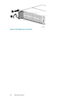
Page 63: ...ive from the enclosure To remove a disk drive 1 Push the ejector button Figure 34 1 and pull the release lever Figure 34 2 down to the full open position 2 Pull the disk drive part way out of the enclosure Figure 34 3 and wait for the media to stop spinning 3 Remove the disk drive from the enclosure Figure 34 3 Figure 34 Removing a disk drive Replacing a disk drive To replace a disk drive 1 Push t...

Page 64: ...Figure 35 Replacing a disk drive 64 Customer self repair ...

Page 65: ...umbers WARNING An assembled enclosure all components installed weighs more than 29 5 kg 65 lb and requires a minimum of two individuals to move Environmental specifications To ensure optimum product operation you must maintain the operational environmental specifications listed in Table 15 The ambient temperature the enclosure air intake or room temperature is especially critical Table 15 Environm...

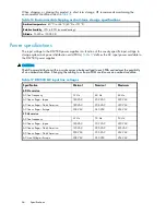
Page 66: ...supplies CAUTION The AC power distribution within a rack ensures a balanced load to each PDA and reduces the possibility of an overload condition Changing the cabling to or from a PDM could cause an overload condition Table 17 DS2500 AC input line voltages Specification Minimal Nominal Maximum 60 Hz service AC line frequency 57 Hz 60 Hz 63 Hz AC line voltage Japan 180 VAC 202 VAC 220 VAC AC line v...

Page 67: ...urrent 5 13 VDC 1 0 A 5 18 VDC N A 5 23 VDC 26 0 A 12 2 VDC Disk drive voltage Initial voltage steady state current 12 13 VDC 1 0 A 12 25 VDC N A 12 37 VDC 26 0 A 12 5 VDC Disk drive voltage Initial voltage steady state current 12 25 VDC 0 0 A 12 50 VDC N A 12 75 VDC 2 0 A Table 20 Power specifications Voltage Current Power Maximum continuous current 5 1 VDC with a minimum 12 2 VDC load of 0A 26 0...

Page 68: ...68 Specifications ...

Page 69: ...res may be required to correct the interference Any modifications to this device unless approved by the manufacturer can void the user s authority to operate this equipment under Part 15 of the FCC rules Class A equipment This equipment has been tested and found to comply with the limits for a Class A digital device pursuant to Part 15 of the FCC Rules These limits are designed to provide reasonab...

Page 70: ...nector hoods in order to maintain compliance with FCC Rules and Regulations Laser devices All Hewlett Packard systems equipped with a laser device comply with safety standards including International Electrotechnical Commission IEC 825 With specific regard to the laser the equipment complies with laser product performance standards set by government agencies as a Class 1 laser product The product ...

Page 71: ...s du Règlement sur le matériel brouilleur du Canada Class B equipment This Class B digital apparatus meets all requirements of the Canadian Interference Causing Equipment Regulations Cet appareil numérique de la classe B respecte toutes les exigences du Règlement sur le matériel brouilleur du Canada European union notice Products with the CE Marking comply with both the EMC Directive 89 336 EEC an...

Page 72: ...riaal worden hergebruikt op een manier waarmee de volksgezondheid en het milieu worden beschermd Neem contact op met uw gemeente het afvalinzamelingsbedrijf of de winkel waar u het product hebt gekocht voor meer informatie over inzamelingspunten waar u oude apparatuur kunt aanbieden voor recycling Czechoslovakian notice Likvidace zařízení soukromými domácími uživateli v Evropské unii Tento symbol ...

Page 73: ...enir plus d informations sur les centres de collecte et de recyclage des appareils mis au rebut veuillez contacter les autorités locales de votre région les services de collecte des ordures ménagères ou le magasin dans lequel vous avez acheté ce produit German notice Entsorgung von Altgeräten aus privaten Haushalten in der EU Das Symbol auf dem Produkt oder seiner Verpackung weist darauf hin dass ...

Page 74: ...ciclo delle apparecchiature da smaltire permette di proteggere la salute degli individui e l ecosistema Per ulteriori informazioni relative ai punti di raccolta delle apparecchiature contattare l ente locale per lo smaltimento dei rifiuti oppure il negozio presso il quale è stato acquistato il prodotto Latvian notice Nolietotu iekārtu iznīcināšanas noteikumi lietotājiem Eiropas Savienības privātaj...

Page 75: ...erá feita de uma forma segura protegendo o ambiente e a saúde das pessoas Para obter mais informações sobre locais que reciclam esse tipo de material entre em contato com o escritório da HP em sua cidade com o serviço de coleta de lixo ou com a loja em que o produto foi adquirido Slovakian notice Likvidácia vyradených zariadení v domácnostiach v Európskej únii Symbol na výrobku alebo jeho balení o...

Page 76: ...clado póngase en contacto con su ayuntamiento con el servicio de eliminación de residuos domésticos o con el establecimiento en el que adquirió el producto Swedish notice Bortskaffande av avfallsprodukter från användare i privathushåll inom Europeiska Unionen Om den här symbolen visas på produkten eller förpackningen betyder det att produkten inte får slängas på samma ställe som hushållssopor I st...

Page 77: ...es the regulations with which the product complies NOTE Components without an individual product certification label are qualified as part of the next higher assembly for example enclosure rack or tower Figure 36 Typical enclosure certification label NOTE The certification symbols on the label depend upon the certification level For example the FCC Class A certification symbol is not the same as t...

Page 78: ...78 Regulatory notices ...

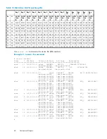
Page 79: ...an error code ec which defines a specific problem NOTE The conventions used to differentiate between the bytes of the condition report are Element type Period after each character 0 1 Element number Period after the second character 01 Error code No periods 01 Table 21 lists the element type codes assigned to the DS2500 components Table 21 Element type Element type et Component 0 1 Disk drive 0 2 ...

Page 80: ...pable of operating at a link rate established by the I O module 0 1 en 02 Information Drive is missing from bay en 1 If the bay is empty install a drive or a drive blank 2 Reseat the drive to ensure that it is properly installed 3 Install a replacement drive or drive blank 0 1 en 03 Information Drive removed after the HP UX software activated the drive lock Unlock the drive using HP UX software 0 ...

Page 81: ...ven if the power supply has failed leave it in the enclosure until a replacement is available 0 2 en 03 Critical Unbalanced power supply load A component in power supply en has failed 1 Verify that the blower on the power supply is functioning properly If not replace the blower 2 Replace the power supply as soon as possible Blower error conditions The format of a blower error condition report is 0...

Page 82: ...ure in 7 minutes unless you install blowers Temperature error conditions The format of a temperature sensor condition report is 0 4 en ec where 0 4 identifies a temperature sensor error en identifies the location of the affected temperature sensor ec provides details about the error See Table 25 to determine the location of each temperature sensor Table 25 Temperature sensor element numbers Elemen...

Page 83: ... Verify that the ambient temperature is in the range of 10 C to 35 C 50 F to 95 F 2 Contact your HP authorized service representative 0 4 en 05 Unrecoverable The EMU has determined that the average temperature of two of the three component areas EMU disk drives and power supplies exceeds the critical level Enclosure shutdown is imminent An automatic shutdown and possible data corruption may result...

Page 84: ...Information EMU internal ESI data corrupted None 0 7 01 17 Unrecoverable A power supply did not respond to an EMU or power supply shutdown command 1 Disconnect the AC power cord from the power supply 2 Contact your HP authorized service representative 0 7 01 18 Unrecoverable EMU internal hardware problem Contact your HP authorized service representative Resetting the EMU If your HP authorized serv...

Page 85: ... transceiver en has been removed Install a new transceiver 0 F en 05 Critical An invalid Fibre Channel character was detected in the incoming data stream on transceiver en Contact your HP authorized service representative Voltage sensor and current sensor error conditions The format of a sensor error condition reports is 1 2 en ec for a voltage sensor and 1 3 en ec for a current sensor where 1 2 i...

Page 86: ...hold for high current Contact your HP authorized service representative Backplane error conditions The format of a backplane error condition report is 8 2 01 ec where 8 2 identifies a backplane error 01 is the two character backplane element number ec is the error code Table 31 Backplane error conditions Error condition Severity Description Actions 8 2 01 10 Noncritical Invalid backplane NVRAM rea...

Page 87: ...e Channel link speed for the I O module en is not supported 8 7 en 02 Critical I O module en is unable to communicate with the EMU 8 7 en 10 Noncritical I O module en NVRAM read error 8 7 en 1 1 Noncritical I O module NVRAM en write error 8 7 en 12 Noncritical I O module en NVRAM read error 8 7 en 13 Noncritical I O module en has been removed Contact your HP authorized service representative HP St...

Page 88: ...88 EMU generated error condition reports ...

Page 89: ...conventions document 9 text symbols 10 cooling 20 country specific certifications 77 critical error 48 audible alarm 50 current sensors 85 customer self repair 1 1 customer self repair CSR 55 blower 59 defective part return 57 disk drive 61 power supply 57 spare part procurement 57 D DC power specifications 67 disk drive 21 status indicators 22 non operational 51 adding 36 error conditions 80 inst...

Page 90: ...mity 70 modifications 70 FCC Class A certification 69 features 13 Federal Communications Commission FCC notice 69 fiber optic cables 19 dust covers 57 firmware revision Fr EMU 42 function select push button 18 H heartbeat icon 49 heat dissipation specifications 65 help obtaining 10 high availability storage system monitor 45 HP storage web site 1 1 Subscriber s choice web site 1 1 technical suppor...

Page 91: ... part procurement 57 specifications environmental 65 physical 65 power 66 status LEDs See LEDs Subscriber s choice HP 1 1 symbols in text 10 T technical support HP 10 temperature ambient 83 error condition 82 sensing 21 sensors 53 warning and shutdown 53 text symbols 10 transceiver 24 error conditions 84 status 50 troubleshooting 45 U unrecoverable error 48 audible alarm 50 V voltage sensors 85 W ...

Reviews: