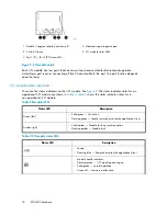
HSV300 controller status LEDs
Figure 13
shows the location of the controller status LEDs;
Table 7
describes them.
1
2
3
4
5
6
gl0114
Figure 13 Controller status LEDs
Table 7 Controller status LEDs
Indication
LED
Item
Blue LED used to identify a certain controller within the en-
closure.
1
Controller health OK. Solid green LED after boot.
2
Solid amber LED used to identify a controller failure either
from a voltage issue or driven by firmware.
3
Not used.
N/A
4
Cache status. Slow flashing green LED shows cache is being
powered by standby power.
5
Cache battery status. Slow flashing amber when cache is
being powered by battery (during AC power loss). Faster
flashing amber when testing. Solid amber when the controller
determines a battery fault.
6
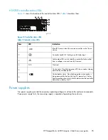
Power supplies
Two power supplies provide the necessary operating voltages to all controller enclosure components.
If one power supply fails, the remaining supply is capable of operating the enclosure.
HP StorageWorks 4400 Enterprise Virtual Array user guide
25
Summary of Contents for StorageWorks 4400
Page 10: ...10 ...
Page 36: ...EVA4400 hardware 36 ...
Page 48: ...EVA4400 operation 48 ...
Page 54: ...Replacing array components 54 ...
Page 92: ...Error messages 92 ...
Page 104: ...Regulatory notices 104 ...
Page 124: ...Glossary 124 ...
Page 128: ...128 ...

