Product Overview 29
Product Over
view
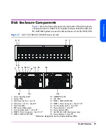
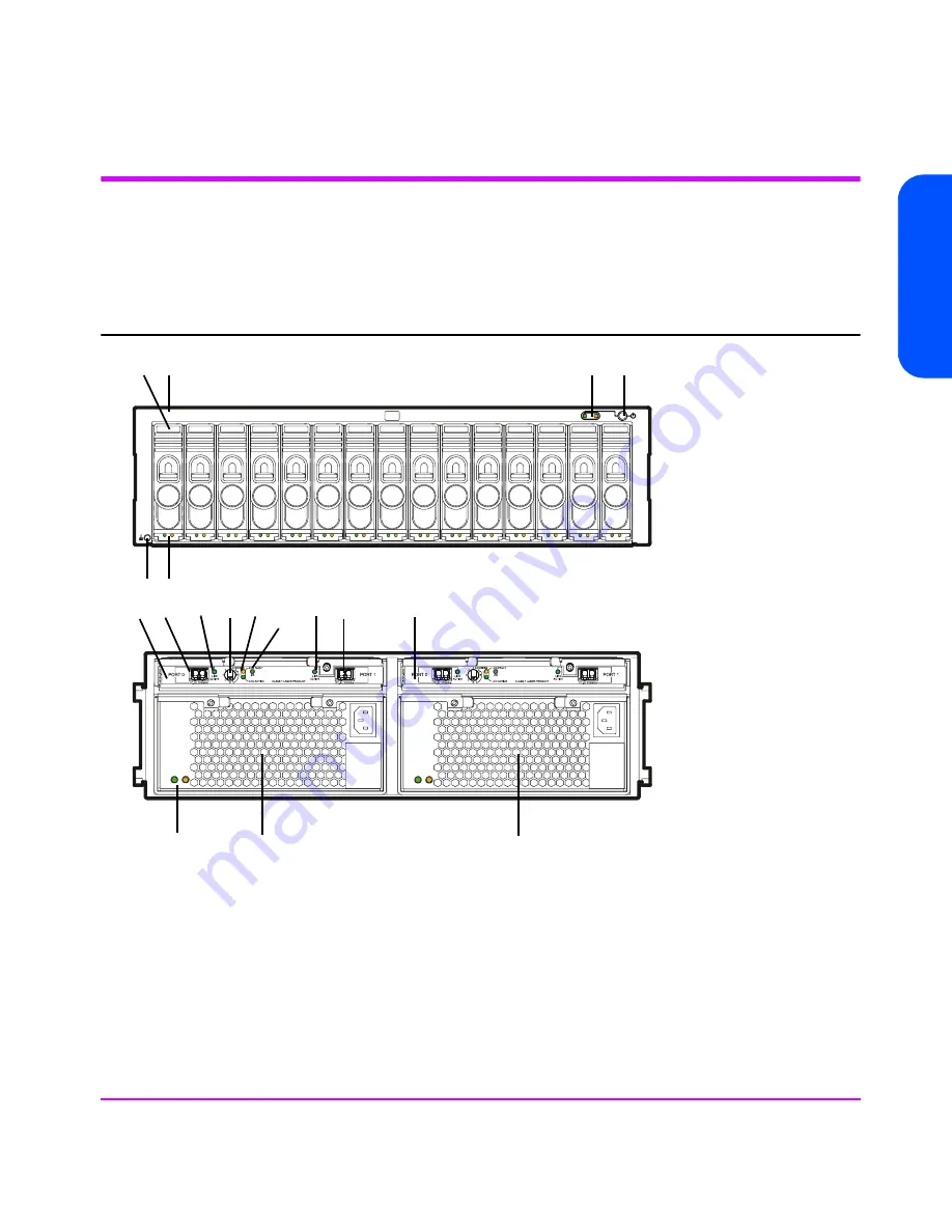
Disk Enclosure Components
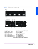
Figure 7
shows the front and rear panel components of the disk enclosure
connected to the VA 7400/7410 controller enclosure. Both DS 2400 and
DS 2405 Disk Systems are used as disk enclosures on the VA 7400/7410.
Figure 7
VA 7110/7400/7410 Disk Enclosure (A/AZ)
*Reference designator used in CommandView SDM
1 - Power/Standby Switch
10 - ADDRESS Switch
2 - System LEDs
11 - LCC LEDs
3 - Disk Drive Slot No. 1 (of 15)
12 - PORT 1 LINK ACTIVE LED
4 - Disk Drive 1 (of 15) - JAn/D1*
13 - PORT 1 FC-AL Connector - JAn/C1.J2*
5 - Disk Drive LEDs
14 - Link Controller Card 2 - JAn/C2*
6 - ESD Ground Receptacle
15 - Power Module 1 - JAn/P1*
7 - Link Controller Card 1 - JAn/C1*
16 - Power Module LEDs
8 - PORT 0 FC-AL Connector - JAn/C1.J1*
17 - 2G LED (DS 2405 Disk System only)
9 - PORT 0 LINK ACTIVE LED
18 - Power Module 2 - JAn/P2*
1
2
3
4
5
6
9
8
10 11
16
15
18
7
12 13
14
17
Summary of Contents for StorageWorks 7110 - Virtual Array
Page 12: ...12 Contents ...
Page 54: ...54 Product Overview Figure 21 VA 7110 I O Architecture ...
Page 90: ...90 Troubleshooting ...
Page 116: ...116 Servicing Upgrading Figure 45 Removing Installing an Array Controller Filler Panel 1 2 3 ...
Page 129: ...Servicing Upgrading 129 Servicing Upgrading Figure 52 Removing and Installing an LCC 1 2 3 ...
Page 130: ...130 Servicing Upgrading Figure 53 Setting the FC Loop Speed Switch Must be set to 1GB s ...
Page 149: ...Specifications Regulatory Statements 149 Specifications Regulatory Statements ...
Page 151: ...Specifications Regulatory Statements 151 Specifications Regulatory Statements ...
Page 152: ...152 Specifications Regulatory Statements ...
Page 164: ...164 Index ...


