Product Overview 35
Product Over
view
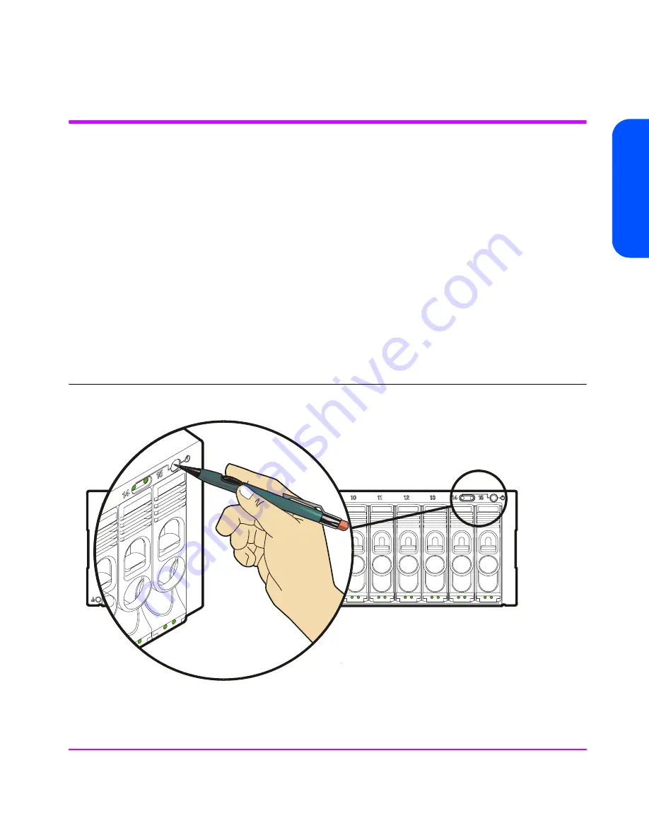
Operating the Power/Standby Switch
When the power/standby switch is in the “power” position, ac power is
applied to the primary and secondary sides of the power supplies in the power
module and all of the dc circuits in the array are active. When the power/
standby switch is in the “standby” position, ac power is only applied to the
primary side of the power supplies; all of the dc circuits in the array are
disabled.
To switch power on, push in the power/standby switch to the “power” position.
See
Figure 11
.To switch power to standby, push in the power/standby switch
then release it to the “standby” position.
Caution
If it is necessary to completely remove power from the array, you
must unplug both power cords from the ac power connectors on
the array rear panel.
Figure 11
Operating the Power/Standby Switch
Summary of Contents for StorageWorks 7110 - Virtual Array
Page 12: ...12 Contents ...
Page 54: ...54 Product Overview Figure 21 VA 7110 I O Architecture ...
Page 90: ...90 Troubleshooting ...
Page 116: ...116 Servicing Upgrading Figure 45 Removing Installing an Array Controller Filler Panel 1 2 3 ...
Page 129: ...Servicing Upgrading 129 Servicing Upgrading Figure 52 Removing and Installing an LCC 1 2 3 ...
Page 130: ...130 Servicing Upgrading Figure 53 Setting the FC Loop Speed Switch Must be set to 1GB s ...
Page 149: ...Specifications Regulatory Statements 149 Specifications Regulatory Statements ...
Page 151: ...Specifications Regulatory Statements 151 Specifications Regulatory Statements ...
Page 152: ...152 Specifications Regulatory Statements ...
Page 164: ...164 Index ...


