


36 Product Overview
Power-On Self-Test
Immediately after the array is powered on, the controller enclosure and disk
enclosures (VA 7400/7410 only) perform a power-on self-test.
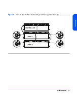
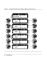
During a power-on self-test, you will see the following front panel activity:
■
The system power/activity LED turns on solid green.
■
The disk drive activity LEDs flash while the controller establishes
communication with the drives, then two LEDs at a time turn on solid green,
one from the lower disk drive slots (1-8) and one from the upper disk drive
slots (9-15), while the associated drives spin up.
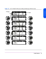
When the power-on self-test completes successfully:
■
All LEDs on the front panel should be solid green.
Shutdown
The coordinated shutdown process is used to take the array offline. The
primary function of shutdown is to copy the contents of the NVRAM to the
image disks. This protects the array against data loss if a battery fails in the
absence of ac power. In the shutdown state, the array can still respond to
management commands from the host, but the host cannot access any of the
data in the array.
During shutdown, the array will use the contents of the controller NVRAM if
valid. For a dual controller configuration only a single NVRAM image is
required to be valid.
Note
If the NVRAM image is not valid the array will enter an error
state. The configuration information and the write cache have
been lost. Access to the data requires a Recover process.
Recovery will attempt to recover the configuration information
from the data disks. The contents of the write cache are not
recoverable.
A shutdown is automatically initiated in two ways:
■
By moving the power/standby switch to the standby position.
■
Using the array management software.
Summary of Contents for StorageWorks 7110 - Virtual Array
Page 12: ...12 Contents ...
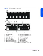
Page 54: ...54 Product Overview Figure 21 VA 7110 I O Architecture ...
Page 90: ...90 Troubleshooting ...
Page 116: ...116 Servicing Upgrading Figure 45 Removing Installing an Array Controller Filler Panel 1 2 3 ...
Page 129: ...Servicing Upgrading 129 Servicing Upgrading Figure 52 Removing and Installing an LCC 1 2 3 ...
Page 130: ...130 Servicing Upgrading Figure 53 Setting the FC Loop Speed Switch Must be set to 1GB s ...
Page 149: ...Specifications Regulatory Statements 149 Specifications Regulatory Statements ...
Page 151: ...Specifications Regulatory Statements 151 Specifications Regulatory Statements ...
Page 152: ...152 Specifications Regulatory Statements ...
Page 164: ...164 Index ...


