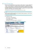
background image

Racking procedures

1.

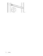
Position left and right rack rails at the desired 'U' position in the rack, adjusting the rails to fit the
rack, as needed (1).
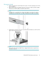
2.

Secure rack rails to the front and back rack columns using screws. Make sure that the shoulders
of the screws fit inside the square or round holes of the rack (2).

NOTE:

If installing rails in a square hole rack, use larger-sized shoulder screws and pins for mounting.
If installing rails in a round hole rack, use smaller-sized shoulder screws and pins for mounting.
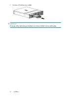
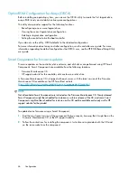
3.

Slide the device into position on the rails (1) and then tighten the thumbscrews on the front of the
device to secure the device to the rack.

NOTE:

The rear ends of the rails have a bracket that must engage the device chassis to secure the rear
of the chassis to the rails.

D2600/D2700 Disk Enclosure User Guide

31

Summary of Contents for StorageWorks D2700

Page 1: ...ure User Guide Smart Array P212 P411 Controller Environments This guide describes the D2600 D2700 6Gb SAS disk enclosure Installation cabling and configuration procedures are also included Part number 504227 001 First edition September 2009 ...

Page 2: ...ments accompanying such products and services Nothing herein should be construed as constituting an additional warranty HP shall not be liable for technical or editorial errors or omissions contained herein WARRANTY STATEMENT To obtain a copy of the warranty for this product see the warranty information website http www hp com go storagewarranty Microsoft Windows Windows XP and Windows NT are U S ...

Page 3: ...fication UID button 19 Power on standby button 19 SAS cables 20 2 Technical specifications 21 General specifications 21 Power and environmental specifications 21 3 Installation 23 Installation overview 23 Required items 23 Preliminary tasks 24 Determining who will install and configure the disk enclosure 24 Saving the disk enclosure website as a favorite in your browser 24 Confirming support for y...

Page 4: ...he operating status of the servers and SAS controllers 42 4 Configuration 43 Configuration overview 43 Configuration best practices 43 Supported software tools 43 HP Systems Insight Manager 44 HP Array Configuration Utility 45 Option ROM Configuration for Arrays ORCA 46 Smart Components for firmware updates 46 5 Operation and management 47 Powering on disk enclosures 47 Powering off disk enclosure...

Page 5: ...ts only warranty service 61 Best practices for replacing hardware components 61 Verifying component failure 61 Identifying the spare part 62 Replaceable parts 62 Replacing the failed component 62 Replacement instructions 63 Exploded view 63 9 Support and other resources 65 Contacting HP 65 Before you contact HP 65 HP contact information 65 Subscription service 65 Documentation feedback 66 Related ...

Page 6: ...1 Bulgarian notice 72 Czech notice 72 Danish notice 72 Dutch notice 72 Estonian notice 73 Finnish notice 73 French notice 73 German notice 73 Greek notice 74 Hungarian notice 74 Italian notice 74 Latvian notice 74 Lithuanian notice 75 Polish notice 75 Portuguese notice 75 Romanian notice 75 Slovak notice 76 Spanish notice 76 Swedish notice 76 Turkish notice 76 Index 77 6 ...

Page 7: ...res can be cascaded from the disk enclosure that is connected to the controller For more information see the QuickSpecs for your enclosure model available at http www hp com go D2000 The enclosure and its components are detailed in the following sections Small Form Factor disk enclosure chassis page 8 Large Form Factor disk enclosure chassis page 9 Disk drives page 11 Front status and UID module p...

Page 8: ... push button and LED 4 I O module A 1 Power supply 1 8 Enclosure status LEDs 5 I O module B 2 Power supply 2 9 Power push button and LED 6 Fan 2 3 Fan 1 Drive bay numbering Disk drives mount in bays on the front of the enclosure Bays are numbered sequentially from top to bottom and left to right Bay numbers are indicated on the left side of each drive bay Hardware 8 ...

Page 9: ...tton and LED 4 I O module A 1 Power supply 1 8 Enclosure status LEDs 5 I O module B 2 Power supply 2 9 Power push button and LED 6 Fan 2 3 Fan 1 Drive bay numbering Disk drives mount in bays on the front of the enclosure Bays are numbered sequentially from top to bottom and left to right A drive bay legend is included on the left bezel D2600 D2700 Disk Enclosure User Guide 9 ...

Page 10: ...Hardware 10 ...

Page 11: ...terns are the same for SFF and LFF disk drives Description LED status LED color LED Used to locate drive Slow blinking Blue 1 Locate Fault Used for critical locate Medium blinking Used for reserved locate Fast blinking Drive fault Solid Amber Drive is spinning up or down and is not ready Blinking Green 2 Status Drive activity Fast blinking Ready for activity Solid Disk drive blanks To maintain the...

Page 12: ...erforming POST Blinking Normal power is on Solid Normal no fault conditions Off Amber 2 Fault A fault of lesser importance was detected in the enclosure chassis or modules Blinking A fault of greater importance was detected in the enclosure chassis or modules Solid Not being identified or power is off Off Blue 3 UID Unit is being identified from the management utility Blinking Unit is being identi...

Page 13: ...session from the management utility can also illuminate the UID To turn on the UID light press the UID button The UID light on the front and the rear of the enclosure will illuminate solid blue The UID on cascaded storage enclosures are not illuminated To turn off an illuminated UID light press the UID button The UID light on the front and the rear of the enclosure will turn off D2600 D2700 Disk E...

Page 14: ...the remaining power supply is capable of operating the enclosure Replace any failed component as soon as possible NOTE If one of the two power supply modules fails it can be hot replaced Power supply LED One LED provides module status information Description LED status LED color No power Off Off Normal no fault conditions Solid Green Hardware 14 ...

Page 15: ...led component as soon as possible NOTE If one of the two fan modules fail it can be hot replaced Fan module LED One bi color LED provides module status information Description LED status LED color No power Off Off The module is being identified Blinking Green Normal no fault conditions Solid Fault conditions detected Blinking Amber Problems detecting the module Solid D2600 D2700 Disk Enclosure Use...

Page 16: ...al operation Large Form Factor I O module Small Form Factor I O module 4 Double 7 segment display 1 Manufacturing diagnostic port 5 I O module LEDs 2 SAS Port 1 3 SAS Port 2 I O module LEDs LEDs on the I O module provide status information about each I O port and the entire module NOTE The following image illustrates LEDs on the Small Form Factor I O module Hardware 16 ...

Page 17: ...the I O module Solid No cable no power enclosure not detected Off n a n a 3 7 segment dis play The enclosure box number Number Not being identified or no power Off Blue 4 UID Module is being identified from the management utility Solid No power or firmware malfunc tion Off Green 5 Health Enclosure is starting up and not ready performing POST Blinking Normal power is on Solid Normal no fault condit...

Page 18: ...r no power Off Blue 1 UID Unit is being identified either from the UID button being pushed or from the management utility On No power Off Green 2 Health Enclosure is starting up and not ready perform ing POST Blinking Normal power is on Solid Normal no fault condi tions Off Amber 3 Fault A fault of lesser import ance Blinking A fault of greater import ance Solid Power is on Solid Green 4 On Standb...

Page 19: ...e enclosure will turn off Power on standby button The power on standby button applies either full or partial power to the enclosure chassis To initially power on the enclosure press and hold the on standby button for a few seconds until the LEDs begin to illuminate To place an enclosure in standby press and hold the on standby button for a few seconds until the on standby LED changes to amber NOTE...

Page 20: ...SAS cables These disk enclosures use cables with mini SAS connectors for connections to the controller and cascaded disk enclosures Hardware 20 ...

Page 21: ...e humidity Rh 28ºC 82 4ºF Maximum wet bulb temperature non condensing Operating Relative humidity Non operating maximum humidity of 95 is based on a temperature of 45 C 113 F Altitude maximum for storage cor responds to a pressure minimum of 70 KPa 5 to 95 relative humidity Rh Non operating 3048 m 10 000 ft This value might be limited by the type and number of options installed Operating Altitude ...

Page 22: ...Technical specifications 22 ...

Page 23: ...rating status of the devices page 41 Required items Items required for installation include the following some of which ship with the disk enclosure Rack mounting kit Disk enclosure Disk drives and drive blanks 6Gb SAS controller SAS cables Power cables Access to a workstation on the server Access to the Internet NOTE A variety of disk drives 6Gb SAS controllers and SAS cables are supported for us...

Page 24: ...re installation and activation of optional software Array initialization Verification that the implemented solution meets your specifications Availability of an HP Services Storage Specialist to answer questions during the deployment process Verification testing to confirm product functionality and adherence to HP installation quality standards On site orientation including highlights of basic ope...

Page 25: ...ll range of HP products services and promotions for public sector with customized additions just for higher education K 12 and federal gov ernment State and Local Solutions magazine Learn how state and local governments are harnessing technology to better serve citizens with fewer resources Includes case studies products pro motions and services Online classes Learning center Register for online c...

Page 26: ...p information Planning the storage configuration Proper planning of the system storage and its subsequent performance is critical to a successful deployment of the disk enclosure Improper planning or implementation can result in wasted storage space degraded performance or inability to expand the system to meet growing storage needs Considerations include System and performance expectations Stripi...

Page 27: ...ount of physical disk space used and I O speed After you create a LUN you cannot change the RAID level The following table compares the different RAID levels RAID meth od Data redund ancy Best practices Summary Striping None IMPORTANT Do not use RAID0 for LUNs if fault tolerance is re quired Consider RAID0 only for noncritical storage RAID0 LUNs provide the best performance for applications that u...

Page 28: ...using parity information from the other member disks During the rebuilding process the array is operating in a reduced state and unless it is a RAID6 or RAID1 0 array it cannot tolerate another disk failure in the same array If another disk fails at this time the array becomes inaccessible and information stored there must be restored from backup After the rebuild of the data onto the spare is com...

Page 29: ...t Home page of the HP servers website nl http www hp com country us eng prodserv servers html Providing adequate clearance space and ventilation Be sure to provide adequate clearance around the front and back of the racks Provide at least 63 5 cm 25 in in the front of the rack to allow the doors to open fully and provide at least 76 2 cm 30 in in the rear of the rack to allow for servicing and air...

Page 30: ...se enclosures switches and servers are of differing depths if you have more than one of a device mount those devices adjacent to one another to accommodate working behind the rack WARNING To reduce the risk of personal injury or damage to the equipment be sure that At least two people lift the storage system during removal or installation if the weight exceeds 22 7 kg 50 lb If the system is being ...

Page 31: ...TE If installing rails in a square hole rack use larger sized shoulder screws and pins for mounting If installing rails in a round hole rack use smaller sized shoulder screws and pins for mounting 3 Slide the device into position on the rails 1 and then tighten the thumbscrews on the front of the device to secure the device to the rack NOTE The rear ends of the rails have a bracket that must engag...

Page 32: ...Installation 32 ...

Page 33: ...tton and pull the drive only slightly out of the enclosure Then to allow time for the internal disk to stop rotating wait approximately 10 seconds before completely removing the drive from the enclosure Disk drives are hot pluggable A variety of disk drive models are supported for use including dual ported SAS disk drives and single ported SATA disk drives For more information about supported disk...

Page 34: ...3 Continue until all drives are installed IMPORTANT For proper airflow and cooling a drive blank must remain installed in all unused drive bays Installation 34 ...

Page 35: ...000 website http www hp com go D2000 Install all operating system specific service packs patch kits or other required tools Install HP system management and monitoring tools such as HP Systems Insight Manager HP SIM and the Array Configuration Utility ACU Install one or more Smart Array controller in the server that will access the disk enclosure For in structions see the documentation provided wi...

Page 36: ...ther the cables in the rear of the disk enclosure to ensure that the cabling in the back of the rack system does not interfere with system operation or maintenance Bind the cables loosely with cable ties and route the excess cables out of the way along the side of the rack When the cables are tied together and routed down the side of the rack system components and indicators are easily visible and...

Page 37: ...e I O module B in the disk enclosure is not supported for use The following illustration shows an HP ProLiant DL380 G6 server with a two port HP Smart Array P411 controller connecting to Small Form Factor SFF disk enclosures Your environment might include a different model server controller or disk enclosure but the cabling principles are the same For additional examples of cabling scenarios see C...

Page 38: ...h HP Smart Array P212 or P411 controllers the second I O module I O module B is not supported for use Use provided color clues on the disk enclosure when cabling cascaded disk enclosures for example connect green ports to green ports connect I O module A on one disk enclosure to I O module A on the additional disk enclosure The following illustration shows an HP ProLiant DL380 G6 server with an HP...

Page 39: ...e is restored or relocated Depending on the cause and duration of the power outage you can use this time to properly shut down your storage sub system Disk enclosure power supplies connected to two separate power sources Protects you from downtime when one of the disk enclosure power supplies fails Protects you from data loss when one or both of your power sources fails due to a pulled cable tripp...

Page 40: ... the power on standby button on the rear of the disk enclosures until the system power LED illuminates solid green The LED on the power on standby button changes from amber to solid green indicating that the disk enclosure has transitioned from a standby state to fully powered 3 Wait a few minutes for the disk enclosures to complete their startup routines CAUTION If power is applied to the server ...

Page 41: ...re information about disk enclosure LEDs see Chapter 1 on page 7 Fault condition Operating condition Startup condi tion LED Disk enclosure component Off Solid green Blinking green 1 Health Front UID module L E D s Blinking or Solid Amber Off Blinking amber 2 Fault Off Off Blinking blue 3 UID Off Solid green Green Status Power supply module Blinking or solid amber Solid green Solid green Status Fan...

Page 42: ... Remove and reinsert the module Verify the operating status of the servers and SAS controllers Verify that the server is operating properly A simple test is to verify that the operating system loaded and then open a software application or browser If the server is not operating properly see the documentation that came with the server for help Installation 42 ...

Page 43: ...ng the redundancy level Identifying the operating system type also called Host Mode or Profile of the host that will access the disk enclosure This ensures that the disk enclosure will communicate properly with that host Verifying that the configured storage is visible to the host Configuration best practices Maintain detailed records of your storage network including information about the hosts a...

Page 44: ...re and pre failure and collects data for reporting and graphing SIM also provides base level management of HP clients printers and selected storage HP recommends using HP SIM to monitor the performance of your systems NOTE You must install and use SIM to benefit from the Pre Failure Warranty for processors SAS SCSI and SATA disk drives and memory modules Key SIM benefits include System discovery a...

Page 45: ...access rights to disk enclosures by hosts Supports local or remote access NOTE When creating arrays using the graphical user interface the ACU provides easy to use configuration wizards and suggested settings Consider these defaults especially the RAID level and rebuild priority and make sure that they are acceptable according to your plans For information about using the ACU see the ACU section o...

Page 46: ...mart Components Smart Components are available from the following locations Firmware Maintenance CD HP support website for the controller disk enclosure or disk drive A Firmware Maintenance CD is shipped with each server with the latest version of the Firmware Maintenance CD available on the HP SmartStart website nl http h18006 www1 hp com products servers management smartstart NOTE Not all availa...

Page 47: ...y button on the rear of the disk enclosures until the system power LED illuminates solid green The LED on the power on standby button changes from amber to solid green indicating that the disk enclosure has transitioned from a standby state to fully powered 3 Wait a few minutes for the disk enclosures to complete their startup routines CAUTION If power is applied to the server before the disk encl...

Page 48: ...firmware After initial installation and periodically after that verify that the controller disk enclosure and disk drives are running on the latest available firmware You can identify currently installed firmware versions through the HP SIM and ACU software utilities Firmware updates on the controller disk enclosure and disk drives are performed using HP Smart Components For more information see S...

Page 49: ...6 Cabling examples Large Form Factor D2600 disk enclosures Smart Array P411 controller Single I O path D2600 D2700 Disk Enclosure User Guide 49 ...

Page 50: ...Large Form Factor D2600 disk enclosures Smart Array P411 controller Single I O path Maximum configuration Cabling examples 50 ...

Page 51: ...Large Form Factor D2600 disk enclosures Smart Array P212 controller Single I O path Maximum configuration D2600 D2700 Disk Enclosure User Guide 51 ...

Page 52: ...Small Form Factor D2700 disk enclosures Smart Array P411 controller Single I O path Cabling examples 52 ...

Page 53: ...Small Form Factor D2700 disk enclosures Smart Array P411 controller Single I O path Maximum configuration D2600 D2700 Disk Enclosure User Guide 53 ...

Page 54: ...Small Form Factor D2700 disk enclosures Smart Array P212 controller Single I O path Maximum configuration Cabling examples 54 ...

Page 55: ...ry remove and reinstall the power supplies to verify that they are seated properly b Remove and inspect AC power cords from both power supplies and reconnect them Diagnostic steps Is the enclosure front fault LED amber Actions Possible Reasons Answer No action required System functioning properly No Be sure that the Front Status and UID module is undamaged and is fully seated Check rear fault LEDs...

Page 56: ...ware updates on page 46 Contact an authorized service provider for assistance The power on standby button has not been pressed firmly or held long enough The system might have experi enced a short Controller firm ware might be corrupted The system midplane and or power button LED assembly might need to be replaced Yes Is the power supply LED amber Actions Possible Reasons Answers Remove and inspec...

Page 57: ...een Removing an active I O module can result in data loss Contact an authorized service provider for assistance The I O module is locked The I O module has failed Other fault condition exists Yes Is the fan LED amber Actions Possible Reasons Answers No action required Functioning properly No Be sure that the fan is undam aged and is fully seated Contact an authorized service provider for assistanc...

Page 58: ...e with no spares assigned RAID6 with ADG configurations can tolerate simultaneous failure of two drives with no spares assigned Compromised fault tolerance If more disk drives fail than the fault tolerance method allows fault tolerance is compromised and the logical drive fails Factors to consider before replacing disk drives Before replacing a degraded drive Open HP SIM and inspect the Error Coun...

Page 59: ...the rebuild is given over normal I O operations you can change the priority setting by using ACU The amount of I O activity during the rebuild operation The rotational speed of the disk drives The availability of drive cache The model and age of the drives The amount of unused capacity on the drives The number of drives in the array for RAID5 and RAID6 with ADG Allow approximately 5 minutes per gi...

Page 60: ...rives perform a normal shutdown 3 Remove the failed drive and replace it with a drive that is of the same capacity For hot plug drives after you secure the drive in the bay the LEDs on the drive each flash once in an alternating pattern to indicate a successful connection The online LED flashes indicating that the controller recognized the drive replacement and began the recovery process 4 Power u...

Page 61: ...s on your storage system successfully CAUTION Removing a component significantly changes the air flow within the enclosure Components or a blanking panel must be installed for the enclosure to cool properly If a component fails leave it in place in the enclosure until a new component is available to install Verifying component failure Consult HP technical support to verify that the hardware compon...

Page 62: ...his product see the warranty information website http www hp com go storagewarranty To order a replacement part contact an HP authorized service provider or see the HP Parts Store online http www hp com buy parts Replacing the failed component CAUTION Components can be damaged by electrostatic discharge ESD Use proper anti static protection Always transport and store CRUs in an ESD protective encl...

Page 63: ...ked on or oth erwise compressed Replacement instructions Printed instructions are shipped with the replacement part Instructions for all replaceable components are also posted to the HP website http www hp com support manuals Exploded view D2600 D2700 Disk Enclosure User Guide 63 ...

Page 64: ...upply Mandatory 5 I O module Mandatory 6 Backplane Mandatory 7 Fan module Mandatory 8 Fan module interconnect board Not a CSR part 9 Drive cage Mandatory 10 Rear power UID module To order a replacement part contact an HP authorized service provider or see the HP Parts Store online http www hp com buy parts Replacement procedures 64 ...

Page 65: ... HP United States website nl http welcome hp com country us en contact_us html To contact HP by phone Call 1 800 HP INVENT 1 800 474 6836 This service is available 24 hours a day 7 days a week For continuous quality improvement calls might be recorded or monitored If you have purchased a Care Pack service upgrade call 1 800 633 3600 For more inform ation about Care Packs see the HP website nl http...

Page 66: ... Cross reference links and e mail addresses Blue text Document conventions and symbols Website addresses Blue underlined text http www hp com Keys that are pressed Text typed into a GUI element such as a box GUI elements that are clicked or selected such as menu and list items buttons tabs and check boxes Bold text Text emphasis Italic text File and directory names System output Code Commands thei...

Page 67: ...ovider will determine whether a repair can be accomplished by CSR For more information about CSR contact your local service provider or see the CSR website nl http www hp com go selfrepair This product has no customer replaceable components Rack stability Rack stability protects personnel and equipment WARNING To reduce the risk of personal injury or damage to equipment Extend leveling jacks to th...

Page 68: ...Support and other resources 68 ...

Page 69: ...ing upon their intended installation Class A devices are those that might reasonably be expected to be installed in a business or commercial environment Class B devices are those that might reasonably be expected to be installed in a residential environment for example personal computers The FCC requires devices in both classes to bear a label indicating the interference potential of the device as...

Page 70: ...Cet appareil numérique de la class A respecte toutes les exigences du Règlement sur le matériel brouilleur du Canada European Union notice This product complies with the following EU directives Low Voltage Directive 2006 95 EC EMC Directive 2004 108 EC Compliance with these directives implies conformity to applicable harmonized European standards European Norms which are listed on the EU Declarati...

Page 71: ...Japanese power cord statement Korean notices Class A equipment Taiwanese notices BSMI Class A notice Chinese notice Recycling notices English notice D2600 D2700 Disk Enclosure User Guide 71 ...

Page 72: ...Bulgarian notice Czech notice Danish notice Dutch notice Regulatory compliance notices 72 ...

Page 73: ...Estonian notice Finnish notice French notice German notice D2600 D2700 Disk Enclosure User Guide 73 ...

Page 74: ...Greek notice Hungarian notice Italian notice Latvian notice Regulatory compliance notices 74 ...

Page 75: ...Lithuanian notice Polish notice Portuguese notice Romanian notice D2600 D2700 Disk Enclosure User Guide 75 ...

Page 76: ...Slovak notice Spanish notice Swedish notice Turkish notice Türkiye Cumhuriyeti EEE Yönetmeli ine Uygundur Regulatory compliance notices 76 ...

Page 77: ...s documentation 66 text symbols 66 converting rack rails for round hole racks 31 Customer Self Repair CSR defined 61 67 parts list 62 website 67 D diagnostic steps 55 if the enclosure does not initialize 55 if the enclosure front fault LED is amber 55 if the enclosure rear fault LED is amber 56 if the fan LED is amber 57 if the I O module fault LED is amber 57 if the power on standby LED is amber ...

Page 78: ...components 24 confirming warranty support 25 identifying system components 26 installation 24 preparing the siteinformation 29 recording information 26 signing up for email alerts 25 the storage configuration 26 using the overview poster 26 power applying to the disk enclosure 40 47 connecting power cords 39 protection against failure table 39 providing redundant sources 29 startup sequence 40 47 ...

Page 79: ... module disk drives 11 fan module 15 front status and UID module 12 I O module 16 power supply module 14 structural support 29 Subscriber s Choice HP 65 website 25 symbols in text 66 T Taiwanese notices 71 technical support HP 65 service locator website 66 text symbols 66 troubleshooting powering up 55 U UID button front 13 rear 19 utilities supported 43 V ventilation requirements 29 verifying the...

Page 80: ...80 ...

Reviews: