background image

7.

Repeat the process to enter the remaining password characters.

8.

Press

Enter

to enter the password and return to the default display.

Clearing a password

Use the following procedure to remove storage system password protection.

NOTE:

Changing a system password on the controller requires changing the password on any

HP Command View EVA with access to the storage system.

1.

Press

four times to scroll to the System Password menu.

2.

Press

to display Change Password?

3.

Press

to scroll to Clear Password.

4.

Press

to display Clear Password.

5.

Press

Enter

to clear the password.

The Password cleared message will be displayed.

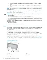
Power supplies

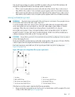
Two power supplies provide the necessary operating voltages to all controller enclosure components.
If one power supply fails, the remaining supply is capable of operating the enclosure.

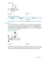
Figure 23 Power supplies

2. Power supply 0

1. Status indicator

3. Power supply 1

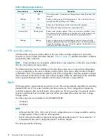
Table 22 Power supply status indicators

Description

Status indicator

Normal operation

Green

Power supply failure

Amber

The power cord is disconnected from the power supply

Flashing amber

Blowers

Two blowers provide the cooling necessary to maintain the proper operating temperature within
the controller enclosure. If one blower fails, the remaining blower is capable of cooling the enclosure.

56

Enterprise Virtual Array hardware components

Summary of Contents for StorageWorks EVA4000

Page 1: ...the HP 4x00 6x00 8x000 Enterprise Virtual Array This document is intended for customers who operate and manage the EVA4x00 6x00 8x00 storage systems This document applies to the EVA4000 6000 8000 and EVA4100 6100 8100 models only HP Part Number 5697 0733 Published March 201 1 Edition 1 1 ...

Page 2: ...ucts and services Nothing herein should be construed as constituting an additional warranty HP shall not be liable for technical or editorial errors or omissions contained herein Warranty To obtain a copy of the warranty for this product see the warranty information website http www hp com go storagewarranty Acknowledgements Microsoft and Windows are U S registered trademarks of Microsoft Corporat...

Page 3: ...nnection configurations 21 Fabric connect iSCSI 21 Direct connect iSCSI 21 Procedures for getting started 22 Gathering information 22 Host information 22 Setting up a controller pair using the OCP 22 Entering the WWN 23 Entering the WWN checksum 24 Entering the storage system password 24 Installing HP Command View EVA 25 Installing optional EVA software licenses 25 3 Enterprise Virtual Array hardw...

Page 4: ... Navigating the error condition display 42 Reporting group feature 43 Reporting group numbers 43 Fibre Channel loop switches 44 30 10022 01 loop switch 44 Power on self test POST 45 30 10010 02 loop switch 45 Power on self test POST 46 Reading the switch status indicators 46 Problem isolation 47 HSV controllers 47 High availability features 49 Operator control panel 49 Status indicators 50 Navigat...

Page 5: ...wn and startup 69 Shutting down the storage system 69 Starting the storage system 70 Saving storage system configuration data 70 Adding disk drives to the storage system 72 Guidelines for adding disk drives 72 Creating disk groups 73 Adding a disk drive 74 Removing the drive blank 74 Changing the Device Addition Policy 74 Installing the disk drive 75 Checking status indicators 75 Adding the disk t...

Page 6: ...Sun SAN driver stack 89 Configuring Emulex FCAs with the lpfc driver 90 Configuring QLogic FCAs with the qla2300 driver 91 Fabric setup and zoning 93 Sun StorEdge Traffic Manager MPxIO Sun Storage Multipathing 93 Configuring with Veritas Volume Manager 93 Configuring virtual disks from the host 95 Verifying virtual disks from the host 96 Labeling and partitioning the devices 97 VMware 98 Installin...

Page 7: ...s 111 Compliance with CDRH regulations 111 Certification and classification information 112 Canadien notice avis Canadien 112 Class A equipment 112 Class B equipment 112 European union notice 112 Notice for France 112 WEEE Recycling Notices 113 English notice 113 Dutch notice 113 Czechoslovakian notice 113 Estonian notice 113 Finnish notice 113 French notice 114 German notice 114 Greek notice 114 ...

Page 8: ...n 03 NONCRITICAL condition Low temperature 129 0 4 en 04 CRITICAL condition Low temperature 129 0 4 en 05 UNRECOVERABLE condition High temperature 129 EMU conditions 130 Resetting the EMU 130 07 01 01 CRITICAL condition EMU internal clock 130 07 01 02 UNRECOVERABLE condition EMU interrupted 130 0 7 01 03 UNRECOVERABLE Condition Power supply shutdown 131 0 7 01 04 INFORMATION condition EMU internal...

Page 9: ...ondition I O module communication 138 8 7 en 10 NONCRITICAL condition I O module NVRAM read 138 8 7 en 1 1 NONCRITICAL condition I O module NVRAM write 139 8 7 en 12 NONCRITICAL condition I O Module NVRAM read failure 139 8 7 en 13 NONCRITICAL condition I O module removed 139 Host conditions 139 C Controller fault management 140 Using HP Command View EVA 140 GUI termination event display 140 GUI e...

Page 10: ...tion 155 Risks 155 Limitations 155 SUN Solaris configuration 156 Requirements 156 HBA configuration 156 Risks 156 Limitations 157 Tru64 UNIX configuration 157 Requirements 157 HBA configuration 157 Risks 158 OpenVMS configuration 158 Requirements 158 HBA configuration 158 Risks 159 Limitations 159 Linux 32 bit configuration 159 Requirements 159 HBA configuration 159 Risks 160 Limitations 160 Linux...

Page 11: ...Failure scenarios 163 HP UX 163 Windows Server 164 Sun Solaris 164 OpenVMS and Tru64 UNIX 165 Linux 165 IBM AIX 166 VMware 166 Glossary 168 Index 180 Contents 1 1 ...

Page 12: ...includes two HSV210 B controllers and four Fibre Channel loop switches EVA6000 6100 available in configurations ranging from the 2C4D configuration to the 2C8D configuration The EVA6000 includes two HSV200 A controllers and two Fibre Channel loop switches The EVA6100 includes two HSV200 B controllers with two Fibre Channel loop switches EVA4000 4100 available in configurations ranging from the 2C1...

Page 13: ...rom the HSV controllers to the SAN Support for 4 Gb host bus adapters and switches Virtualization technology Vraid enables data to be distributed from 8 to 240 disks to increase disk spindle count far beyond traditional RAID sets This virtualization method also optimizes storage for the best performance of a specific configuration and application Enterprise Virtual Array eliminates tedious managem...

Page 14: ... for environments with 1 50 servers Ideal for customers who can benefit from proactive notification but do not need proactive service delivery and integration with a management platform HP Insight Remote Support Advanced This software provides comprehensive remote monitoring and proactive service support for nearly all HP servers storage network and SAN environments plus selected non HP servers th...

Page 15: ... demand improves performance increases disk utilization efficiency and allows for easy dynamic storage expansion XCS is installed on the storage system and is also included in the XCS for HSV Controller software kit XCS features and functionality Support for up to 240 disk drives per controller pair Management of up to 1024 virtual disks ranging in size from 1 GB to 2 TB per virtual disk per disk ...

Page 16: ...nnel loop switches Provides twelve port central interconnect for Fibre Channel drive enclosure FC Arbitrated Loops The loop switches are required for EVA6000 6100 and EVA8000 8100 configurations with more than four disk enclosures HSV controller Manages all aspects of storage system operation including communications between host systems and other devices A pair of HSV controllers is included in t...

Page 17: ...The hardware components shown in Figure 1 page 16 are described in the following sections and in Enterprise Virtual Array hardware components page 26 Storage system components 17 ...

Page 18: ...nts of the storage solution The HSV210 A and HSV210 B controllers connect via four host ports FP1 FP2 FP3 and FP4 to the Fibre Channel fabrics The hosts that will access the storage system are connected to the same fabrics The HP Command View EVA management server also connects to the fabric The controllers connect through two loop pairs to the drive enclosures Each loop pair consists of two indep...

Page 19: ...igure 3 EVA6000 6100 configuration 8 Controller A 1 Network interconnection 9 Controller B 2 Management server 10 Cache mirror ports 3 Non host 1 1 FC loop switch 4 Host X 12 Drive enclosure 1 5 Host Z 13 Drive enclosure 2 6 Fabric 1 7 Fabric 2 EVA4000 4100 storage system connections Figure 4 page 20 shows a typical EVA 4000 4100 SAN topology The HSV200 A and HSV200 B controllers connect via two h...

Page 20: ...A controller The management host must use dual HBAs for redundancy To provide redundancy it is recommended that dual HBAs be used for each additional host connected to the storage system Using this configuration up to four hosts including the management host can be connected to an EVA8x00 and up to two hosts can be connected to an EVA6x00 or EVA4x00 The Host Port Configuration must be set to Direc...

Page 21: ...ler The Host Port Configuration must be set to Fabric Connect using the OCP HP Continuous Access EVA is supported on the same storage system connected in MPX100 fabric connect configurations Direct connect iSCSI Direct connect provides a lower cost solution for configurations that want to dedicate controller ports to iSCSI I O When using direct connect the storage system controllers are connected ...

Page 22: ...mmand View EVA software Check the HP Enterprise Virtual Array Compatibility Reference for controller software and HP Command View EVA compatibility Locate these items and keep them handy You will need them for the procedures in this manual Host information Make a list of information for each host computer that will be accessing the storage system You will need the following information for each ho...

Page 23: ...ed ENTER Entering the WWN Fibre Channel protocol requires that each controller pair have a unique WWN This 16 character alphanumeric name identifies the controller pair on the storage system Two WWN labels attached to the rack identify the storage system WWN and checksum See Figure 5 page 23 NOTE The WWN is unique to a controller pair and cannot be used for any other controller pair or device anyw...

Page 24: ...d The storage system password feature enables you to restrict management access to the storage system The password must meet the following requirements 8 to 16 characters in length Can include upper or lower case letters Can include numbers 0 9 Can include the following characters amp _ Cannot include the following characters space NOTE You must be running HP Command View EVA 6 0 or later to use p...

Page 25: ...rage software html See the HP Command View EVA Installation Guide for information on installing the software Installing optional EVA software licenses If you purchased optional EVA software it will be necessary to install the license Optional software available for the Enterprise Virtual Array includes HP Business Copy EVA and HP Continuous Access EVA Installation instructions are included with th...

Page 26: ... drive blanks Dual redundant power supplies Dual redundant blowers Cache batteries Environmental Monitoring Unit EMU Enclosure layout The disk drives mount in bays in the front of the enclosure The bays are numbered sequentially from left to right A drive is referred to by its bay number Enclosure status indicators are located in the lower right front corner Figure 6 page 26 shows the front and re...

Page 27: ... at the right end of the enclosure and module B can only be installed at the left end of the enclosure See Figure 6 page 26 Each I O module has two ports that can both transmit and receive data for bidirectional operation Activating a port requires connecting a FC cable to the port The port function depends upon the loop See Figure 8 page 27 Figure 8 Input and output ports 2 Loop A upper port 1 Lo...

Page 28: ...es to configurations with and without FC loop switches Off On On Top port No Fibre Channel drive enclosure signal detected Check transceiver and fiber cable connections Power Present Bottom port Fibre Channel drive enclosure signal detected On On Off Top port EMU detected possible transceiver problem Check transceiver and fiber cable connections Power Present Bottom port Fibre Channel drive enclos...

Page 29: ...Optic Fibre Channel cable Copper Fibre Channel cables The Enterprise Virtual Array uses copper Fibre Channel cables to connect the drive enclosures to each other or to the loop switches and to the HSV controllers The cables are available in 0 6 meter and 2 0 meter lengths Copper cables provide performance comparable to fiber optic cables Copper cable connectors differ from fiber optic small form f...

Page 30: ... enclosure Online This amber status indicator is on when there is a disk drive failure Depending on the host controller this indicator may flash when the controller detects an error condition The amber status indicator flashes in synchronization with the other two status indicators in response to the EMU locate command Fault Disk drive status displays The disk drive status indicators can assume th...

Page 31: ...lies and blowers This section describes the function and operation of the disk enclosure power supplies and blowers Figure 12 page 31 illustrates the major power supply and cooling components Figure 12 Power supply and blower assembly components 1 Power supply 2 Status indicator 3 AC Input connector with bail 4 Module latch red wine colored 5 Blower tabs red wine colored 6 Blower Power supplies Th...

Page 32: ... a higher speed Simultaneously the error condition is reported in several ways including the power supply indicator the audible alarm the enclosure fault indicators and the EMU alphanumeric display Should both blowers fail the power supplies automatically shut down NOTE The blowers are field replaceable units and can be replaced individually while the system is running The blowers are also interch...

Page 33: ...lay group function The indicator is on when an error condition exists 4 Display group select button This button is used to view display groups and control the audible alarm The indicator is on when the audible alarm is muted or disabled 5 RS232 For use by HP authorized service representatives 6 LCD ONLY Unused 7 CAB ONLY Enclosure address bus connector WARNING To reduce the risk of electrical shoc...

Page 34: ...pe Revision level Installation Removal Status I O module 5 VDC voltage and current 12 VDC voltage and current Total power Temperature Installation Removal Status Type Revision level Power supplies Link status Type Transceiver EMU displays The EMU uses a combination of status indicators alphanumeric display and an audible alarm to indicate the operational status of the enclosure and its components ...

Page 35: ...re is no enclosure fault Off On On There is an EMU fault There is no enclosure fault Off On Off There is an enclosure fault Either 5 VDC is incorrect or both 5 VDC and 12 VDC are incorrect Other error conditions may exist Off Off Off Using the alphanumeric display The two character alphanumeric display is located at the top of the EMU see Figure 13 page 33 This seven segment display provides infor...

Page 36: ...t an address or state or view a condition report EMU pushbutton status indicators The pushbutton status indicators display error conditions and the state of the audible alarm When an error condition exists the top pushbutton status indicator is On For a single error condition the status indicator is On until the error condition is viewed For multiple errors the status indicator is On until the las...

Page 37: ...display from displaying Er nor does it prevent HP Command View EVA from displaying the error condition report When the alarm is enabled on the bottom push button status indicator is off Enabling the audible alarm To enable the alarm 1 Press and release the bottom push button until the alphanumeric display is Au 2 Press and hold the top push button until the alphanumeric display is a Flashing oF Au...

Page 38: ...cator is now on NOTE A disabled audible alarm the bottom push button indicator is on cannot sound for any error condition To ensure that you are immediately alerted to error conditions it is recommended that the alarm mute function be used rather than the alarm disable function If you must use the disable function remember to enable the audible alarm as soon as possible to ensure that you are aler...

Page 39: ...enclosure ID expansion cables that interconnect the drive enclosures and controller enclosures Two drive enclosures connect to each enclosure ID expansion cable The drive enclosure numbers are always assigned by the enclosure address bus Connecting the EMU CAB connector to an enclosure address bus enclosure ID expansion cable automatically establishes an enclosure number of 01 through 14 Any drive...

Page 40: ...osure 5 8 Shelf ID expansion cable port 8 Disk enclosure 8 7 Shelf ID expansion cable port 7 Controller enclosures 10 Shelf ID expansion cable port 10 Disk enclosure 10 9 Shelf ID expansion cable port 9 Disk enclosure 9 12 Shelf ID expansion cable port 12 Disk enclosure 12 1 1 Shelf ID expansion cable port 1 1 Disk enclosure 1 1 13 Shelf ID expansion cable port 13 Disk enclosure 13 Error Condition...

Page 41: ...to prevent system degradation Information the least severe condition indicates a condition exists that does not reduce the capability of a component However the condition can become an error and require corrective action An INFORMATION condition provides an early warning which enables you to prepare to implement corrective action before a component fails Correction of the reported problem may be d...

Page 42: ...m The format for this display is en with a period after the second character Error code The third display is a two digit decimal number that defines the specific error code The format for this display is ec without any periods For detailed information about each condition report including recommended corrective actions see EMU generated condition reports page 122 Navigating the error condition dis...

Page 43: ...ically assigns a unique decimal four digit Reporting Group Number RGN to each EMU on a Fibre Channel drive enclosure Each of the drive enclosures on a loop pair are in one reporting group All of the drive enclosures on loop pair 1 both loop 1A and loop 1B share a unique reporting group number All of the drive enclosures on loop pair 2 both loop 2A and loop 2B share a unique reporting group number ...

Page 44: ...uses four loop switches and the EVA6000 6100 uses two switches to connect the drive enclosures to the controller pair The loop switches provide the following features 2 125 Gbps operating speed Twelve ports Half width 1U size System and port status indicators Universal power supply that operates between 100 to 250 VAC and 50 to 60 Hz NOTE Each bezel covers two FC loop switches in a space of 1U The...

Page 45: ...ention Fault On the internal temperature has exceeded acceptable levels The switch will continue to operate Switch functionality may be impaired depending on the event that triggered the Temp condition Regardless of the cause the switch requires immediate attention Temp Power on self test POST When the switch powers on it runs Power On Self Test POST diagnostics to verify the fundamental integrity...

Page 46: ...the switch status indicators Figure 18 page 46 shows the Fibre Channel switch with the system and port indicators Table 14 page 46 lists and describes the system indicators Table 14 30 10010 02 loop switch status indicators Description System indicator A green indicator When lit this indicates that the switch is plugged in and the internal power is functional Power A green indicator When lit this ...

Page 47: ... are lit Re seat the SFP If the same condition occurs the SFP is probably faulty and should be replaced SFP is installed but the Port Bypassed indicator is lit This condition indicates that the switch is not receiving a valid Fibre Channel signal or that the switch is receiving an LIP 1 Ensure that the switch is powered on 2 Contact your HP authorized service representative for further assistance ...

Page 48: ...view of both controllers is shown in Figure 21 page 49 NOTE The EVA4000 6000 8000 and EVA4100 6100 8100 use controllers with 2 Gb and 4 Gb host port capability The 4 Gb controller can be distinguished from the earlier 2 Gb controllers by the A and B suffixes used on the controller bezel The 4 Gb EVA4000 and EVA6000 controllers are identified as the HSV200 A The 4 Gb EVA4100 and EVA6100 are identif...

Page 49: ...o Loop A and two Loop B data paths For EVA4x00 and EVA6x00 configurations data redundancy is accomplished with device loop switches on the two Loop A data paths Each HSV210 A B controller has two lead acid cache batteries that provide power to the cache memory Each HSV200 A B controller has one battery When the batteries are fully charged they can provide power to the cache for up to 96 hours Oper...

Page 50: ...When this indicator is green there is at least one physical link between the storage system and hosts that is active and functioning normally When this indicator is off there are no links between the storage system and hosts that are active and functioning normally Physical link to hosts established When this indicator is green all virtual disks that are presented to hosts are healthy and function...

Page 51: ...reference names regardless of labels are left right top and bottom Table 19 Navigation button functions Function Button Moves down through the available menus and options Moves up through the available menus and options Selects the displayed menu or option Returns to the previous menu Used for No selections and to return to the default display Esc Used for Yes selections and to progress through me...

Page 52: ...revious menu NOTE To exit any menu press Esc or wait ten seconds for the OCP display to return to the default display Table 20 page 52 identifies all the menu options available within the OCP display CAUTION Many of the configuration settings available through the OCP impact the operating characteristics of the storage system You should not change any setting unless you understand how it will impa...

Page 53: ...isplays the Versions Menu tree To display System Information 1 The default display alternates between the Storage System Name display and the World Wide Name display Press any push button to display the Storage System Menu Tree 2 Press until the desired Versions Menu option appears and then press or to move to submenu items Shutting down the system CAUTION To power off the system for more than 96 ...

Page 54: ...educes the risk of accidentally powering down NOTE HP Command View EVA is the preferred method for shutting down the controller Shut down the controller from the OCP only if HP Command View EVA cannot communicate with the controller Shutting down the controller from the OCP removes power from the controller on which the procedure is performed only To restore power toggle the controller s power 1 P...

Page 55: ...ess ESC the system does not uninitialize The bottom OCP line displays Uninit cancelled Password options The password entry options are Entering a password during storage system initialization see Entering the storage system password page 24 Displaying the current password Changing a password see Changing a password page 55 Removing password protection see Clearing a password page 56 Changing a pas...

Page 56: ...rd The Password cleared message will be displayed Power supplies Two power supplies provide the necessary operating voltages to all controller enclosure components If one power supply fails the remaining supply is capable of operating the enclosure Figure 23 Power supplies 2 Power supply 0 1 Status indicator 3 Power supply 1 Table 22 Power supply status indicators Description Status indicator Norm...

Page 57: ...atteries are used on the EVA8x00 and a single battery is used on the EVA6x00 and EVA4x00 Figure 25 page 57 illustrates the location of the cache batteries and the battery status indicators See Table 24 page 58 for additional information on the status indicators Figure 25 Cache batteries 2 Fault indicator 1 Status indicator 4 Battery 1 3 Battery 0 The table below describes the battery status indica...

Page 58: ...not indicate whether there is communication on the link only whether the link can transmit and receive data The data connections are the interfaces to the disk drive enclosures or loop switches depending on your configuration the other controller and the fabric Fiber optic cables link the controllers to the fabric and if an expansion cabinet is part of the configuration link the expansion cabinet ...

Page 59: ...he rack The characteristics of the fully redundant rack power configuration are as follows Each PDU is connected to a separate circuit breaker protected 30 A AC site power source 220 240 VAC 10 50 or 60 Hz 5 Figure 26 page 59 illustrates the compatible 60 Hz and 50 Hz wall receptacles Figure 26 60 Hz and 50 Hz wall receptacles NEMA L6 30R receptacle 3 wire 30 A 60 Hz IEC 309 receptacle 3 wire 30 A...

Page 60: ... Be put into production Remain in this state for more than 24 hours PDUs Each Enterprise Virtual Array rack has either a 50 or 60 Hz dual PDU mounted at the bottom rear of the rack The 228481 002 228481 003 PDU placement is back to back plugs facing down with switches on top The standard 50 Hz PDU cable has an IEC 309 3 wire 30 A 50 Hz connector The standard 60 Hz PDU cable has a NEMA L6 30P 3 wir...

Page 61: ...n the left vertical rail connect to PDU 1 Three mounted on the right vertical rail connect to PDU 2 Each PDM has eight AC receptacles and one thermal circuit breaker The PDMs distribute the AC power from the PDUs to the enclosures Two power sources exist for each controller pair and drive enclosure If a PDU fails the system will remain operational CAUTION The AC power distribution within a rack en...

Page 62: ...igure 29 Rack AC power distribution 2 PDM 2 1 PDM 1 4 PDU 1 3 PDM 3 6 PDM 5 5 PDM 4 8 PDU 2 7 PDM 6 Rack System E power distribution components AC power is distributed to the Rack System E rack through Power Distribution Units PDU mounted on the two vertical rails in the rear of the rack Up to four PDUs can be mounted in the rack two mounted on the right side of the cabinet and two mounted on the ...

Page 63: ...potential for it to tip over Moving the rack requires a clear uncarpeted pathway that is at least 80 cm 31 5 in wide for the 60 3 cm 23 7 in wide 42U rack A vertical clearance of 203 2 cm 80 in should ensure sufficient clearance for the 200 cm 78 7 in high 42U rack CAUTION Ensure that no vertical or horizontal restrictions exist that would prevent rack movement without damaging the rack Make sure ...

Page 64: ...page 63 To stabilize the rack when it is in the final installation location 1 Use a wrench to lower the foot by turning the leveler foot hex nut clockwise until the caster does not touch the floor Repeat for the other feet 2 After lowering the feet check the rack to ensure it is stable and level 3 Adjust the feet as necessary to ensure the rack is stable and level 64 Enterprise Virtual Array hardw...

Page 65: ...ally disconnect the host port from its existing connection change the topology setting and then reconnect the host port For example to change from a fabric switched topology to a direct connect topology do the following 1 Disconnect the host port s from the Fibre Channel switch 2 Using the operator control panel OCP change the controller host port mode from fabric to direct connect 3 Connect the h...

Page 66: ...ing the MPIO DSM CLI Microsoft is currently working on a resolution to address this issue Connecting to C series switches If C series switches are not set correctly the EVA host ports may not log back in to the fabric after changes occur in the fabric This issue involves the following C series switch model families 90xx 91xx 92xx and 95xx You may also need to restart the controller if you move the...

Page 67: ... surviving controller There is no failback except if a host moves the LUN using SCSI commands On controller failback The units are brought online to Controller B At initial presentation Path B Failover Only If cache data for a LUN exists on a particular controller the unit will be brought online there Otherwise the units are brought online to Controller B On dual boot or controller resynch All LUN...

Page 68: ... Recommended settings may vary depending on your configuration or environment Table 26 Failback Settings by operating system Supported settings Default behavior Operating system No Preference Path A B Failover Only Path A B Failover Failback Host follows the unit1 HP UX No Preference Path A B Failover Only Path A B Failover Failback Host follows the unit1 IBM AIX No Preference Path A B Failover On...

Page 69: ...on controller A it is moved to controller B If the disk is on controller B it remains there Path B Failover Failback Storage system shutdown and startup The storage system is shut down using HP Command View EVA The shutdown process performs the following functions in the indicated order 1 Flushes cache 2 Removes power from the controllers 3 Disables cache battery power 4 Removes power from the dri...

Page 70: ...nd the drive online indicator should be on green 5 Power on the upper controller It takes the role of master controller 6 Wait 10 seconds and then power on the lower controller It takes the role of slave controller 7 Verify that the Operator Control Panel OCP display on each controller displays the storage system name and the EVA WWN 8 Start HP Command View EVA and verify connection to the storage...

Page 71: ...is case sensitive If there are spaces between the letters in the name quotes must enclose the name for example SELECT SYSTEM Large EVA 4 Enter CAPTURE CONFIGURATION specifying the full path and filename of the output files for the configuration data The configuration data is stored in a series of from one to five files which are SSSU scripts The file names begin with the name you select with the r...

Page 72: ... To restore the storage system configuration 1 Double click on the SSSU desktop icon to run the application 2 Enter FILE pathname filename where pathname identifies the location where the configuration files are be saved and filename is the name of the first configuration file for example FILE c EVAConfig LargeEVA_Step1A txt 3 Repeat the preceding step for each configuration file Adding disk drive...

Page 73: ...ups are more robust if filled with the same number of disk drives in each enclosure See Figure 33 page 74 for an example NOTE When adding multiple disk drives add a disk and wait for its activity indicator 1 to stop flashing up to 90 seconds before installing the next disk see Figure 32 page 73 This procedure must be followed to avoid unexpected EVA system behavior Figure 32 Disk drive activity in...

Page 74: ...ction describes the procedure for adding a Fibre Channel disk drive Removing the drive blank 1 Grasp the drive blank by the two mounting tabs see Figure 34 page 74 2 Lift up on the lower mounting tab and pull the blank out of the enclosure Figure 34 Removing the drive blank 2 Lower mounting tab 1 Upper mounting tab Changing the Device Addition Policy To prevent the storage system from automaticall...

Page 75: ...s Check the following to verify that the disk drive is operating normally NOTE It may take up to 10 minutes for the component to display good status Check the disk drive status indicators See Figure 36 page 76 Activity indicator 1 should be on or flashing Online indicator 2 should be on or flashing Fault indicator 3 should be off Check the following using HP Command View EVA Navigate to the disk d...

Page 76: ...k Disk enclosure Bay 2 In the Content pane select the Disk Drive tab 3 Click Group to initiate the process for adding the disk to a disk group NOTE If the Device Addition Policy is set to automatic the disk will automatically be added to a disk group In this case the Group option will not be available Handling fiber optic cables This section provides protection and cleaning methods for fiber optic...

Page 77: ...overs and dust caps when installing an I O module a transceiver or a cable Install the dust covers when disconnecting a transceiver or cable When to clean If a connector may be contaminated or if a connector has not been protected by a dust cover for an extended period of time clean it How to clean 1 Wipe the connector with a lint free tissue soaked with 100 isopropyl alcohol 2 Wipe the connector ...

Page 78: ...n the host server in order to communicate with the EVA NOTE Traditionally the adapter that connects the host server to the fabric is called a host bus adapter HBA The server HBA used with the EVA4x00 6x00 8x00 is called a Fibre Channel adapter FCA You might also see the adapter called a Fibre Channel host bus adapter Fibre Channel HBA in other related documents Follow the hardware installation rul...

Page 79: ...applicable operating system for the host mode Table 28 Operating system and host mode selection Host mode selection in HP Command View EVA Operating System HP UX HP UX IBM AIX IBM AIX Linux Linux Linux Mac OS X OVMS OpenVMS Sun Solaris Sun Solaris VMware VMware Linux Citrix XenServer Microsoft Windows Microsoft Windows Microsoft Windows 2008 4 Check the Host folder in the Navigation pane of HP Com...

Page 80: ... that the zoning is correct for your configuration Configuring virtual disks from the host After you create the virtual disks on the EVA4x00 6x00 8x00 and rescan or restart the host follow the host specific conventions for configuring these new disk resources For instructions see the documentation included with your server HP UX To create virtual disks for HP UX scan the bus and then create volume...

Page 81: ...irtual group block data allowing HP UX to access the virtual disk See the pvcreate vgcreate and lvcreate man pages for more information about creating disks and file systems Use the following procedure to create a volume group on a virtual disk NOTE Italicized text is for example only 1 To create the physical volume on a virtual disk enter the following command pvcreate f dev rdsk c32t0d1 2 To cre...

Page 82: ...fic Z7 07831914 Device Specific Z8 20000000C940F529 Device Specific Z9 TS1 90A4 Device Specific ZA T1D1 90A4 Device Specific ZB T2D1 90A4 Device Specific YL U0 1 P1 I5 Q1b Creating and presenting virtual disks When creating and presenting virtual disks to an IBM AIX host be sure to 1 Set the OS unit ID to 0 2 Set Preferred path mode to No Preference 3 Select a LUN number if you chose a specific LU...

Page 83: ... for your distribution The driver kit file is in the format hp_qla2x00 yyyy mm dd tar gz 2 Copy the driver kit to the target system 3 Uncompress and untar the driver kit using the following command tar zxvf hp_qla2x00 yyyy mm dd tar gz 4 Change directory to the hp_qla2x00 yyyy mm dd directory 5 Execute the INSTALL command The INSTALL command syntax varies depending on your configuration If a previ...

Page 84: ... driver and install a new driver rpm e fibreutils rpm ivh fibreutils version revision linux architecture rpm Upgrading qla2x00 RPMs If you have a qla2x00 RPM from HP installed on your system use the INSTALL script to upgrade from qla2x00 RPMs The INSTALL script removes the old qla2x00 RPM and installs the new hp_qla2x00src while keeping the driver settings from the previous installation The script...

Page 85: ...o install you will need a development machine with the same kernel as your targeted production servers You can install the binary RPM produced RPM methods on your production servers NOTE The binary RPM that you build works only for the kernel and configuration that you build on and possibly some errata kernels Ensure that you use the 7 xx version of the hp_qla2x00 source RPM for 2 4 kernel based d...

Page 86: ...date procedure varies for the different server types To update firmware follow the procedure described in the Installation instructions that accompany the firmware images Verifying the Fibre Channel adapter software installation A supported FCA should already be installed in the host server The procedure to verify that the console recognizes the installed FCA varies for the different server types ...

Page 87: ...boot Manager select EFI Shell b In the EFI Shell enter Shell drivers A list of EFI drivers loaded in the system is displayed 3 In the listing find the line for the FCA for which you want to get the WWN information For a Qlogic HBA look for HP 4 Gb Fibre Channel Driver or HP 2 Gb Fibre Channel Driver as the driver name For example T D D Y C I R P F A V VERSION E G G D C DRIVER NAME IMAGE NAME 22 00...

Page 88: ...4 Alt type avail HP rx3600 1 59GHz 9 0MB yes Allocation class 1 I O paths to device 9 Path PGA0 5000 1FE1 0027 0A38 BRCK18 primary path Error count 0 Operations completed 145 Path PGA0 5000 1FE1 0027 0A3A BRCK18 Error count 0 Operations completed 338 Path PGA0 5000 1FE1 0027 0A3E BRCK18 Error count 0 Operations completed 276 Path PGA0 5000 1FE1 0027 0A3C BRCK18 Error count 0 Operations completed 2...

Page 89: ...erred path use the following command SET DEVICE 1 DGA83 PATH PGA0 5000 1FE1 0007 9772 SWITCH This allows you to control which path each virtual disk uses To display the path identifiers use the SHOW DEV FULL command For additional information on using OpenVMS commands see the OpenVMS help file HELP TOPIC For example the following command displays help information for the MOUNT command HELP MOUNT S...

Page 90: ...laris 10 Reboot the host once the required software patches have been installed No further activity is required after adding any new LUNs as the controller and LUN recognition are automatic for Solaris 10 1 For Solaris 10 x86 64 ensure patch 138889 03 or later is installed For SPARC ensure patch 138888 03 or later is installed 2 Increase the retry counts by adding the following line to the kernel ...

Page 91: ...h the WWPNs of your array ports 6 For each LUN that will be accessed add an entry to the kernel drv sd conf file For example if you want to access LUNs 1 and 2 through all four paths add the following entries to the end of the file name sd parent lpfc target 20 lun 1 name sd parent lpfc target 21 lun 1 name sd parent lpfc target 30 lun 1 name sd parent lpfc target 31 lun 1 name sd parent lpfc targ...

Page 92: ...array port This ensures that the SCSI target IDs remain the same when the system reboots Set persistent bindings by editing the configuration file or by using the SANsurfer utility NOTE Persistent binding is not required for QLogic FCAs if you are using Solaris 10 The following example for an EVA4x00 6x00 8x00 illustrates the binding of targets 20 and 21 hba instance 0 to WWPNs 50001fe100270938 an...

Page 93: ...Manager MPxIO Sun Storage Multipathing can be used for FCAs configured with the Sun SAN driver and depending on the operating system version architecture SPARC x86 and patch level installed For configuration details see the HP MPxIO application notes available on the HP support website http www hp com support manuals NOTE MPxIO is included in the SPARC and x86 Sun SAN driver A separate installatio...

Page 94: ...libvxhpevale so ATTR_NAME ATTR_VALUE LIBNAME libvxhpevale so VID HP PID HSV200 HSV210 ARRAY_TYPE A A A HP ARRAY_NAME EVA4K6K EVA8000 vxdmpadm listapm all grep HP dmphpalua dmphpalua 1 A A A HP Active vxdmpadm listapm dmphpalua Filename dmphpalua APM name dmphpalua APM version 1 Feature VxVM VxVM version 41 Array Types Supported A A A HP Depending Array Types A A A State Active vxdmpadm listenclosu...

Page 95: ...is displayed after the device address For example 50001fe1002709e9 5 Sun SAN driver without MPxIO The EVA WWPN is part of the file name which helps you to identify the controller For example dev rdsk c3t50001FE1002709E8d5s2 dev rdsk c3t50001FE1002709ECd5s2 dev rdsk c4t50001FE1002709E9d5s2 dev rdsk c4t50001FE1002709EDd5s2 If you use luxadm probe the array node WWN and the associated device files ar...

Page 96: ...and difficult to read For example 09 e8 20 04 00 00 00 00 00 00 35 30 30 30 31 46 50001F 45 31 30 30 32 37 30 39 45 30 35 30 30 30 31 46 E1002709E050001F 45 31 30 30 32 37 30 39 45 38 36 30 30 35 30 38 E1002709E8600508 42 34 30 30 31 30 33 30 45 34 30 30 30 30 35 30 B4001030E4000050 30 30 30 30 42 32 30 30 30 30 00 00 00 00 00 00 0000B20000 The assigned LUN is part of the device file name For exam...

Page 97: ... 0 ssd w50001fe1002709f9 2 7 c3t50001FE1002709FDd1 HSV210 6240 cyl 126 alt 2 hd 128 sec 128 pci 1f 4000 lpfc 5 fp 0 0 ssd w50001fe1002709fd 1 8 c3t50001FE1002709FDd2 HSV210 6240 cyl 126 alt 2 hd 128 sec 128 pci 1f 4000 lpfc 5 fp 0 0 ssd w50001fe1002709fd 2 Specify disk enter its number If you cannot access the virtual disks Verify the zoning For Sun Solaris verify that the correct WWPNs for the EV...

Page 98: ...file and enter the following command upgrade pl 4 Reboot the system using the default boot option esx Configuring the EVA with VMware host servers To configure an EVA4x00 6x00 8x00 on a VMware ESX server 1 Using HP Command View EVA configure a host for one ESX server 2 Verify that the Fibre Channel Adapters FCAs are populated in the world wide port name WWPN list Edit the WWPN if necessary 3 Set t...

Page 99: ...t downloads 1 2 Unzip the file 3 Follow the instructions in the readme file to load the NVRAM configuration onto each FCA Setting the multipathing policy You can set the multipathing policy for each LUN or logical drive on the SAN to one of the following Most recently used MRU Fixed Preferred ESX 2 5 x commands The vmkmultipath s vmhba0 0 1 p mru command sets vmhba0 0 1 with an MRU multipathing po...

Page 100: ...ng DiskMaxLUN The DiskMaxLUN setting specifies the highest numbered LUN that can be scanned by the ESX server For ESX 2 5 x the default value is 8 If more than eight LUNs are presented you must change the setting to an appropriate value To set DiskMaxLUN select Options Advanced Settings in the MUI and then enter the highest numbered LUN For ESX 3 x or ESX 4 x the default value is set to the Max se...

Page 101: ...e virtual disks enter the more proc scsi scsi command The output lists all SCSI devices detected by the server An EVA8100 LUN entry looks similar to the following Host scsi3 Channel 00 ID 00 Lun 01 Vendor HP Model HSV210 Rev Type Direct Access ANSI SCSI revision 02 VMware 101 ...

Page 102: ...re to cool properly If a component fails leave it in place in the enclosure until a new component is available to install Component replacement videos To assist you in replacing the components videos have been produced of the procedures You can view the videos at the following website http www hp com go sml Verifying component failure Consult HP technical support to verify that the hardware compon...

Page 103: ...te or return to depot repair is not provided under warranty Optional CSR You can order the part directly from HP and repair the product yourself or you can request that HP repair the product If you request repair from HP you may be charged for the repair depending on the product warranty No CSR The replaceable part is not available for self repair For assistance contact an HP authorized service pr...

Page 104: ...isk drive 600 GB 15K 366022 001 366022 002 Disk drive 250 GB FATA 382262 001 Disk drive 400 GB FATA 371 142 001 Disk drive 500 GB FATA 454416 001 Disk drive 1 TB 7 2K FATA 408515 001 70 41260 T1 both RoHS Chassis with backplane 390859 001 70 41 143 S1 or 390859 005 70 41 143 T1 Operator control panel 375393 001 70 401 45 S2 375393 005 70 40145 T2 EMU 364549 005 70 406 16 T4 or 364549 009 70 40616 ...

Page 105: ...3 001 70 41 140 S1 41 1632 005 70 41 140 S3 Front panel bezel EVA8000 390854 001 70 41 140 S2 41 1632 006 70 41 140 S5 Front panel bezel EVA8100 41 1633 005 70 41 140 S4 both RoHS Front panel bezel EVA4000 6000 41 1633 006 70 41 140 S6 both RoHS Front panel bezel EVA4100 6100 For more information about CSR contact your local service provider For North America see the CSR website http www hp com go...

Page 106: ...cing removed cables on the floor or other surfaces where they may be walked on or otherwise compressed Replacement procedures are provided with each component You can also download the following replacement instructions from the Manuals page of the HP Business Support Center website See Related information page 107 for more information HP Controller Blower Replacement Instructions HP Controller En...

Page 107: ...ification of product enhancements new driver versions firmware updates and other product resources Documentation feedback HP welcomes your feedback To make comments and suggestions about product documentation please send a message to storagedocsfeedback hp com All submissions become the property of HP Related information Documents You can find related documents from the Manuals page of the HP Busi...

Page 108: ... monospace text Monospace bold text WARNING Indicates that failure to follow directions could result in bodily harm or death CAUTION Indicates that failure to follow directions could result in damage to equipment or data IMPORTANT Provides clarifying information or specific instructions NOTE Provides additional information TIP Provides helpful hints and shortcuts Rack stability WARNING To reduce t...

Page 109: ...tly to you so that you can install it at your convenience Some parts do not qualify for CSR Your HP authorized service provider will determine whether a repair can be accomplished by CSR For more information about CSR contact your local service provider For North America see the CSR website http www hp com go selfrepair Customer self repair 109 ...

Page 110: ...n of this equipment in a residential area may cause interference in which case the user at the user s own expense will be required to take whatever measures may be required to correct the interference Any modifications to this device unless approved by the manufacturer can void the user s authority to operate this equipment under Part 15 of the FCC rules NOTE Additional information on the need to ...

Page 111: ... The FCC requires the user to be notified that any changes or modifications made to this device that are not expressly approved by Hewlett Packard Company may void the user s authority to operate the equipment Cables Connections to this device must be made with shielded cables with metallic RFI EMI connector hoods in order to maintain compliance with FCC Rules and Regulations Laser device All Hewl...

Page 112: ...il numérique de la classe A respecte toutes les exigences du Règlement sur le matériel brouilleur du Canada Class B equipment This Class B digital apparatus meets all requirements of the Canadian Interference Causing Equipment Regulations Cet appareil numérique de la classe B respecte toutes les exigences du Règlement sur le matériel brouilleur du Canada European union notice Products with the CE ...

Page 113: ...linzamelingsbedrijf of de winkel waar u het product hebt gekocht voor meer informatie over inzamelingspunten waar u oude apparatuur kunt aanbieden voor recycling Czechoslovakian notice Likvidace zařízení soukromými domácími uživateli v Evropské unii Tento symbol na produktu nebo balení označuje výrobek který nesmí být vyhozen spolu s ostatním domácím odpadem Povinností uživatele je předat takto oz...

Page 114: ...ment Pour obtenir plus d informations sur les centres de collecte et de recyclage des appareils mis au rebut veuillez contacter les autorités locales de votre région les services de collecte des ordures ménagères ou le magasin dans lequel vous avez acheté ce produit German notice Entsorgung von Altgeräten aus privaten Haushalten in der EU Das Symbol auf dem Produkt oder seiner Verpackung weist dar...

Page 115: ...i apparecchiature elettriche ed elettroniche La raccolta differenziata e il corretto riciclo delle apparecchiature da smaltire permette di proteggere la salute degli individui e l ecosistema Per ulteriori informazioni relative ai punti di raccolta delle apparecchiature contattare l ente locale per lo smaltimento dei rifiuti oppure il negozio presso il quale è stato acquistato il prodotto Latvian n...

Page 116: ...o serviço de coleta de lixo ou com a loja em que o produto foi adquirido Slovakian notice Likvidácia vyradených zariadení v domácnostiach v Európskej únii Symbol na výrobku alebo jeho balení označuje že daný výrobok sa nesmie likvidovať s domovým odpadom Povinnosťou spotrebiteľa je odovzdať vyradené zariadenie v zbernom mieste ktoré je určené na recykláciu vyradených elektrických a elektronických ...

Page 117: ...ortskaffande av avfallsprodukter från användare i privathushåll inom Europeiska Unionen Om den här symbolen visas på produkten eller förpackningen betyder det att produkten inte får slängas på samma ställe som hushållssopor I stället är det ditt ansvar att bortskaffa avfallet genom att överlämna det till ett uppsamlingsställe avsett för återvinning av avfall från elektriska och elektroniska produk...

Page 118: ...ical specifications of the drive enclosure and elements Table 32 page 118 defines the dimensions and weights of the storage system components Table 32 Enterprise Virtual Array 4x00 6x00 8x00 Product Dimensions Weight and Clearance Req Rear Clearance in cm Req Front Clearance in cm Max Weight lb kg Depth in cm Width in cm Height in cm Physical Dimensions 30 76 2 30 76 2 537 244 1 40 2 102 2 23 7 60...

Page 119: ...able 34 Enterprise storage system AC input line voltages Maximum Nominal Minimal Specification 60 Hz service 63 Hz 60 Hz 57 Hz AC Line Voltage 220 VAC 202 VAC 180 VAC AC Line Voltage Japan 220 VAC 208 VAC 180 VAC AC Line Voltage North America 254 VAC 240 VAC 208 VAC AC Line Voltage Europe 50 Hz service 53 Hz 50 Hz 47 Hz AC Line Frequency 220 VAC 202 VAC 180 VAC AC Line Voltage Japan 235 VAC 220 VA...

Page 120: ...ine Failover Mode 1 Typical is described as a system in normal steady state operation i e both PDUs operating normally the array reading writing to disk drives in a production environment This data represents fully populated drive enclosures with 15K RPM disk drives Other drive types may vary slightly For example if you are using 10K RPM drives the power specifications will be approximately 20 les...

Page 121: ... 1 1 3 4 9 Input Current A Maximum per line Failover Mode 1 Typical is described as a system in normal steady state operation i e both PDUs operating normally the array reading writing to disk drives in a production environment This data represents fully populated drive enclosures with 15K RPM disk drives Other drive types may vary slightly For example if you are using 10K RPM drives the power spe...

Page 122: ...at correcting problems and how to identify element types The error codes are arranged in element type sequence that is 0 1 0 2 0 3 etc Condition report format When the EMU alphanumeric display is Er three additional displays identify the possible cause of the problem the element type the specific element and the error code which defines the possible cause of the problem The first level display ide...

Page 123: ... However no direct correlation exists between the disk drive bay number and the device Fibre Channel drive enclosure physical address The Fibre Channel drive enclosure physical address is assigned by negotiation during system initialization The following sections define the disk drive error codes 0 1 en 01 CRITICAL condition Drive configuration or drive link rate As each drive spins up and comes o...

Page 124: ...ized service representative 0 1 en 02 INFORMATION condition Drive missing The drive is improperly installed or missing Either option could affect the enclosure air flow and cause an over temperature condition for another element This error remains active for one minute or until the problem is corrected whichever occurs first Immediate correction is not required However correction cannot be delayed...

Page 125: ...is problem 1 Record all six characters of the condition report 2 Remove and replace the drive in the enclosure 3 Observe the drive status indicators to ensure the drive is operational 4 Observe the EMU to ensure the error is corrected 5 If removing and replacing the drive did not correct the problem replace the drive 6 Observe the drive status indicators to ensure the drive is operational 7 Observ...

Page 126: ...s problem record all six characters of the condition report then contact your authorized service representative CAUTION Removing power from an enclosure may cause the loss or corruption of data To avoid this condition shut down the system using HP Command View EVA An automatic shutdown and possible data corruption may result if the power supply is removed before a replacement is available 0 2 en 0...

Page 127: ...l The error remains active until the problem is corrected HP recommends replacing the blower as soon as possible To correct this problem record all six characters of the condition report then contact your authorized service representative 0 3 en 03 UNRECOVERABLE condition Blower failure A blower has stopped The operational blower now operates at high speed and is a single point of failure This con...

Page 128: ...haracter temperature sensor element ec is the error code See Table 43 page 128 to determine the location of each temperature sensor Table 43 Temperature sensor element numbering Sensor location Sensor Sensor location Sensor Drive Bay 7 10 Power Supply 1 Exhaust 01 Drive Bay 8 1 1 Power Supply 2 Exhaust 02 Drive Bay 9 12 EMU 03 Drive Bay 10 13 Drive Bay 1 04 Drive Bay 1 1 14 Drive Bay 2 05 Drive Ba...

Page 129: ... Low temperature This condition report indicates that an element temperature is approaching but has not reached the low temperature CRITICAL threshold Continued operation under these conditions may result in a CRITICAL condition This condition report remains active until the problem is corrected Complete the following procedure to correct this problem 1 Record all six characters of the condition r...

Page 130: ...is action is required Another option is to reset the EMU using the following procedure 1 Firmly grasp the EMU mounting handle and pull the EMU partially out of the enclosure NOTE You do not need to remove the EMU from the enclosure or disconnect the cables You must avoid putting any strain on the cables or connectors 2 Wait 30 seconds and then push the EMU in and fully seat the element in the back...

Page 131: ...ed or cannot be read by the EMU there is no communication with the disk drives This condition report remains active until the problem is corrected Complete the following procedure to correct this problem 1 Record all six characters of the condition report 2 Reset the EMU 3 Observe the EMU to ensure the error is corrected 4 If resetting the EMU did not correct the problem contact your HP authorized...

Page 132: ...or a defective enclosure address bus enclosure ID expansion cable This condition report remains active until the problem is corrected Complete the following procedure to correct this problem 1 Record all six characters of the condition report 2 Remove and reconnect the cable between the address bus enclosure ID expansion cable and the EMU NOTE The EMU display may not display a change in condition ...

Page 133: ...ndition report remains active until the problem is corrected Complete the following procedure to correct this problem 1 Record all six characters of the condition report 2 Reset the EMU 3 Observe the EMU to ensure the error does not recur within the first minute 4 If the error does recur contact your HP authorized service representative The EMU is inoperative and must be replaced as soon as possib...

Page 134: ...er detect a data signal This error prevents the controller from transferring data on a loop and eliminates the enclosure dual loop capability This error remains active until the problem is fixed To correct this problem record all six characters of the condition report then contact your HP authorized service representative 0 F en 03 CRITICAL condition Transceiver fibre channel drive enclosure bus f...

Page 135: ...n EMU error is to replace the EMU Call your authorized service representative if this action is required Another option is to reset the EMU using the following procedure 1 Firmly grasp the EMU mounting handle and pull the EMU partially out of the enclosure NOTE You do not need to remove the EMU from the enclosure or disconnect the cables You must avoid putting any strain on the cables or connector...

Page 136: ... is the current sensor element type number en is the sensor element number ec is the error code Table 44 page 136 lists the location of the power supply voltage and current sensors Table 44 Voltage and current sensor locations Sensor Element Location Sensor Power Supply 1 5 VDC 01 Power Supply 1 12 VDC 02 Power Supply 2 5 VDC 03 Power Supply 2 12 VDC 04 Use HP Command View EVA to view the voltage ...

Page 137: ...thorized service representative 1 3 en 02 CRITICAL condition High current This condition report indicates that an element current has reached the high current CRITICAL threshold This condition report remains active until the problem is corrected To correct this problem record all six characters of the condition report then contact your HP authorized service representative Backplane conditions IMPO...

Page 138: ...n I O module problem normally requires replacing the module The following sections define the I O module problem by I O module location 8 7 en 01 CRITICAL condition I O module unsupported The I O module Fibre Channel link speed is not supported by the backplane This error prevents the controller from establishing a link with enclosure drives and eliminates the enclosure dual loop capability This c...

Page 139: ... The system is unable to read data from the I O module NVRAM Complete the following procedure to correct this problem 1 Record all six characters of the condition report 2 Contact your HP authorized service representative 8 7 en 13 NONCRITICAL condition I O module removed The system detects that an I O module has been removed To correct the problem install an I O module Host conditions The EMU has...

Page 140: ...play see Figure 45 page 140 to diagnose and correct the problem NOTE The major differences between the Termination Event display and the Event display are The Termination Event display includes a Code Flag field it does not include the EIP Type field The Event display includes an EIP type field it does not include a Code Flag field The Event display includes a Corrective Action Code field Figure 4...

Page 141: ...ormation to determine and implement corrective action You can also provide this information to the authorized service representative should you require additional support This lets the service representative identify the tools and components required to correct the condition in the shortest possible time When the fault management display is active you can either display the last fault or display d...

Page 142: ...able 45 Controller event text description file Description Information type This hexadecimal code identifies the reported event type Event Code This hexadecimal code specifies the condition that generated the termination code It might also define either a system or user initiated corrective action Termination Code TC This single digit decimal character defines the requirement for the other control...

Page 143: ...s such as servers Figure 47 Mounting space dimensions EIA310 D standards The rack must meet the Electronic Industries Association EIA Standard 310 D Cabinets Racks and Associated Equipment The standard defines rack mount spacing and component dimensions specified in U units Copies of the standard are available for purchase at http www eia org EVA cabinet measures and tolerances EVA component rack ...

Page 144: ...loop pair 0 0 875 0 0 47 1 Filler panel 1U 10 64 2 53 0 094 120 4 XL Controller Pair 1 1U 1 75 inches Airflow and Recirculation Component Airflow Requirements Component airflow must be directed from the front of the cabinet to the rear Components vented to discharge airflow from the sides must discharge to the rear of the cabinet Rack Airflow Requirements The following requirements must be met to ...

Page 145: ...6 4 10965 3214 3334 16 0 8 9919 2907 3015 14 5 9680 2837 2943 14 1 7 8633 2530 2625 12 6 8394 2460 2552 12 3 6 7348 2153 2234 10 7 7109 2083 2161 10 4 5 6063 1777 1843 8 9 5824 1707 1770 8 5 5585 1637 1698 8 2 4 4777 1400 1452 7 0 4538 1330 1380 6 6 4300 1260 1307 6 3 3 3492 1023 1062 5 1 3253 953 989 4 8 3014 883 916 4 4 2 2207 647 671 3 2 1968 577 598 2 9 1729 507 526 2 5 1 Table 48 230V Wattage...

Page 146: ...hen selecting a UPS for use with the EVA The four HP UPS products listed in Table 50 page 146 are available for use with the EVA and are included in this comparison Table 51 page 146 identifies the amount of time each UPS can sustain power under varying loads and with various UPS ERM Extended Runtime Module options The load imposed on the UPS for different disk enclosure configurations are listed ...

Page 147: ...4 50 101 69 43 20 Table 52 EVA 8x00 UPS loading of UPS capacity Watts Enclosures R12000 R5500 41 0 4920 12 36 8 98 1 4414 1 1 33 6 89 7 4037 10 30 5 81 3 3660 9 27 4 73 0 3284 8 24 2 64 6 2907 7 21 1 56 2 2530 6 17 9 47 9 2153 5 14 8 39 5 1777 4 1 1 7 31 1 1400 3 8 5 22 7 1023 2 5 4 14 4 647 1 Table 53 EVA 6x00 UPS loading of UPS capacity Watts Enclosures R12000 R5500 R3000 26 8 71 4 3214 8 23 6 6...

Page 148: ... 94 0 1260 3 32 7 65 9 883 2 18 7 37 9 507 1 Environmental specifications Table 55 Environmental specifications 50 to 95 F 10 to 35 C Reduce rating by 1 F for each 1000 ft altitude 1 8 C 1 000 m Operating temperature 40 to 150 F 40 to 66 C Shipping temperature 10 to 90 non condensing Operating humidity 5 to 90 non condensing Shipping humidity Up to 8 000 ft 2 400 m Altitude Not to exceed 500 000 p...

Page 149: ...ing Shock Vibration Shock test with half sine pulses of 10 G magnitude and 10 ms duration applied in all three axes both positive and negative directions Sine sweep vibration from 5 Hz to 500 Hz to 5 Hz at 0 1 G peak with 0 020 displacement limitation below 10 Hz Sweep rate of 1 octave minute Test performed in all three axes Random vibration at 0 25 G rms level with uniform spectrum in the frequen...

Page 150: ... further information on cluster configurations and attributes see the appropriate operating system guides and the SAN design guide NOTE HP continually makes additions to its storage solution product line For more information about the HP Fibre Channel product line the latest drivers and technical tips and to view other documentation see the HP website at http www hp com country us eng prodserv sto...

Page 151: ...backups of the single path server and its storage Supported configurations All examples detail a small homogeneous Storage Area Network SAN for ease of explanation Mixing of dual and single path HBA systems in a heterogeneous SAN is supported In addition to this document reference and adhere to the SAN Design Reference Guide for heterogeneous SANs located at http h18006 www1 hp com products storag...

Page 152: ...presents the fabric zone that must be established for the single path HBA server Note that in Figure 49 page 152 servers with OpenVMS or Tru64 UNIX operating system should be zoned with two controllers Figure 48 Single path HBA server without OpenVMS or Tru64 UNIX 6 SAN switch 2 1 Network interconnection 7 Fabric zone 2 Single HBA server 8 Controller A 3 Dual HBA server 9 Controller B 4 Management...

Page 153: ... present that virtual disk as you would any other ordinary virtual disk HBA configuration Host 1 is a single path HBA host Host 2 is a multiple HBA host with multi pathing software See Figure 50 page 153 Risks Disabled jobs hang and cannot umount disks Path or controller failure may results in loss of data accessibility and loss of host data that has not been written to storage NOTE For additional...

Page 154: ... would any other ordinary virtual disk HBA configuration Host 1 is a single path HBA host Host 2 is a multiple HBA host with multi pathing software See Figure 51 page 154 Risks Single path failure will result in loss of connection with the storage system Single path failure may cause the server to reboot Controller shutdown puts controller in a failed state that results in loss of data accessibili...

Page 155: ...stem will support multiple single path HBAs in the same server This is accomplished through a combination of switch zoning and controller level SSP Any single path HBA server will support up to four single path HBAs Risks Single path failure will result in loss of connection with the storage system Single path failure may cause the server to reboot Controller shutdown puts controller in a failed s...

Page 156: ... single path hosts that are zoned with the same controller In the case of snapclones after the cloning process has completed and the clone becomes an ordinary virtual disk you may present that virtual disk as you would any other ordinary virtual disk HBA must be properly configured to work in a single HBA server configuration The user is required to Download and extract the contents of the TAR fil...

Page 157: ...sive access to its LUNs All nodes with direct connection to a disk must have the same access paths available to them Single HBA server can be in the same fabric as servers with multiple HBAs In the use of snapshots and snapclones the source virtual disk and all associated snapshots and snapclones must be presented to the single host that are zoned with the same controller In the case of snapclones...

Page 158: ...nt server OpenVMS configuration Requirements Switch zoning or controller level SSP must be used to ensure each single path HBA has an exclusive path to its LUNs All nodes with direct connection to a disk must have the same access paths available to them Single path HBA server can be in the same fabric as servers with multiple HBAs In the use of snapshots and snapclones the source virtual disk and ...

Page 159: ...ingle path HBA has an exclusive path to its LUNs All nodes with direct connection to a disk must have the same access paths available to them Single path HBA server can be in the same fabric as servers with multiple HBAs In the use of snapshots and snapclones the source virtual disk and all associated snapshots and snapclones must be presented to the single path hosts that are zoned with the same ...

Page 160: ...on to a disk must have the same access paths available to them Single path HBA server can be in the same fabric as servers with multiple HBAs In the use of snapshots and snapclones the source virtual disk and all associated snapshots and snapclones must be presented to the single path hosts that are zoned with the same controller In the case of snapclones after the cloning process has completed an...

Page 161: ... LUNs Single path HBA server can be in the same fabric as servers with multiple HBAs Single path HBA server cannot share LUNs with any other HBAs In the use of snapshots and snapclones the source virtual disk and all associated snapshots and snapclones must be presented to the single path hosts that are zoned with the same controller In the case of snapclones after the cloning process has complete...

Page 162: ...ontroller A 3 Dual HBA server 8 Controller B 4 Management server VMware configuration Requirements Switch zoning or controller level SSP must be used to ensure each single path HBA has an exclusive path to its LUNs All nodes with direct connection to a disk must have the same access paths available to them Single path HBA server can be in the same fabric as servers with multiple HBAs In the use of...

Page 163: ... 5 SAN switch 1 1 Network interconnection 6 SAN switch 2 2 Single HBA server 7 Controller A 3 Dual HBA server 8 Controller B 4 Management server Failure scenarios HP UX Table 57 HP UX failure scenarios Failure effect Fault stimulus Extremely critical event on UNIX Can cause loss of system disk Server failure host power cycled Short term Data transfer stops Possible I O errors Long term Job hangs c...

Page 164: ...ng operation Controller restart Write delay volume inaccessible Host hangs and restarts Server path failure Write delay volume disappears server still running When cables plugged back in controller recovers server finds volume data loss Storage path failure Sun Solaris Table 59 Sun Solaris failure scenarios Failure effect Fault stimulus Check disk when rebooting Data loss data that finished copyin...

Page 165: ...Mount Verify Timeout No data is lost or corrupted Tru64 UNIX All I O operations halted I O errors are returned back to the applications An I O failure to the system disk can cause the system to panic Possible data loss from unfinished or unflushed writes File system check may be needed upon reboot Server path failure OpenVMS OS will report the volume in a Mount Verify state until the MVTIMEOUT lim...

Page 166: ...ages in errpt output System reboot causes loss of data on disk Must crfs disk Controller restart Short term Data transfer stops Possible I O errors Long term Repeated error messages in errpt output System reboot causes loss of data on disk Must crfs disk Server path failure Short term Data transfer stops Possible I O errors Long term Repeated error messages in errpt output System reboot causes los...

Page 167: ...e reloaded before failed drives can be recovered fsck should be run on any failed drives before remounting Server path failure Short I O suspended possible data loss Long I O halts with I O errors data loss HBA driver must be reloaded before failed drives can be recovered fsck should be run on any failed drives before remounting Storage path failure Failure scenarios 167 ...

Page 168: ...oom temperature ANSI American National Standards Institute A non governmental organization that develops standards such as SCSI I O interface standards and Fibre Channel interface standards used voluntarily by many manufacturers within the United States arbitrated loop A Fibre Channel topology that links multiple ports up to 126 together on a single shared simplex media Transmissions can only occu...

Page 169: ...embly is referred to as a jumper CAC Corrective Action Code An HP Command View EVA graphical user interface GUI display component that defines the action required to correct a problem See also read cache write cache and mirrored cache cache High speed memory that sets aside data as an intermediate data buffer between a host and the storage media The purpose of cache is to improve performance cache...

Page 170: ... the system in initialized The default disk group can contain the entire set of physical disks in the array or just a few of the disks See also disk group Detailed Fault View An HSV Controller OCP display that permits a user to view detailed information about a controller fault device channel A channel used to connect storage devices to a host I O bus adapter or intelligent controller device ports...

Page 171: ...ss 1 2 In the Open SAN Manager a controllable object such as the Enterprise storage system EMI Electromagnetic Interference The impairment of a signal by an electromagnetic disturbance EMU Environmental Monitoring Unit An element which monitors the status of an enclosure including the power air temperature and blower status The EMU detects problems and displays and reports these conditions to a us...

Page 172: ...ber See Evt No Evt No Event Number A sequential number assigned to each Software Code Identification SWCID event It is a decimal number in the range 0 255 exabyte A unit of storage capacity that is the equivalent of 260 bytes or 1 152 921 504 606 846 976 bytes One exabyte is equivalent to 1 024 petabytes F fabric A Fibre Channel fabric or two or more interconnected Fibre Channels allowing data tra...

Page 173: ...internal array of logic blocks surrounded by a ring of programmable I O blocks connected together through a programmable interconnect frequency The number of cycles that occur in one second expressed in Hertz Hz Thus 1 Hz is equivalent to one cycle per second FRU Field Replaceable Unit A hardware element that can be replaced in the field This type of replacement can require special training tools ...

Page 174: ...eographic area laser A device that amplifies light waves and concentrates them in a narrow very intense beam Last Fault View An HSV Controller display defining the last reported fault condition Last Termination Error Array See LTEA License Key A WWN encoded sequence that is obtained from the license key fulfillment website link A connection between ports on Fibre Channel devices The link is a full...

Page 175: ... special open Fibre Channel mechanisms for eye protection The Enterprise storage system transceivers are non OFC compatible NONCRITICAL Condition A drive enclosure EMU condition report that occurs when one or more elements inside the enclosure have failed or are operating outside of their specifications The failure does not affect continued normal operation of the enclosure All devices in the encl...

Page 176: ...identify the unit as hot pluggable port_name A 64 bit unique identifier assigned to each Fibre Channel port The port_name is communicated during the login and port discovery processes power distribution module See PDM power distribution unit See PDU power supply An element that develops DC voltages for operating the storage system elements from either an AC or DC source preferred address An AL_PA ...

Page 177: ...ng the redundant power configuration provides protection against the loss or corruption of data reporting group An Enterprise Storage System controller pair and the associated disk drive enclosures The Enterprise Storage System controller assigns a unique decimal reporting group number to each EMU on its loops Each EMU collects disk drive environmental information from its own sub enclosure and br...

Page 178: ...ransceiver The device that converts electrical signals to optical signals at the point where the fiber cables connect to the FC elements such as hubs controllers or adapters U uninitialized system A state in which the storage system is not ready for use See also initialization UNRECOVERABLE Condition A drive enclosure EMU condition report that occurs when one or more elements inside the enclosure ...

Page 179: ... down into chunks and distributed on the physical disks comprising the disk group in which the virtual disk was created If the striped virtual disk has parity another chunk a parity chunk is calculated from the set of data chunks and written to the physical disks If one of the data chunks becomes corrupted the data can be reconstructed from the parity chunk and the remaining data chunks W World Wi...

Page 180: ...ce statement 1 1 1 cabling controller 58 CAC 140 142 cache battery assembly indicator 50 CAUTIONs initializing the system 55 CDRH compliance regulations 1 1 1 Center for Devices and Radiological Health see CDRH certification product labels 1 18 changing passwords 55 checksum 24 Class A equipment Canadian compliance statement 1 12 Class B equipment Canadian compliance statement 1 12 cleaning fiber ...

Page 181: ...P 93 document conventions 108 documentation providing feedback 107 drive enclosures defined 16 front view 26 drives detecting configuration error 123 detecting drive link error 124 125 detecting link rate error 123 missing 124 monitoring functions 34 reporting conditions 123 dump restart control codes 142 dust covers using 77 dynamic capacity expansion 15 E EIP 141 142 element condition reporting ...

Page 182: ...42 firmware version display 53 functions monitoring 34 H hardware components 16 harmonics conformance Japan 1 17 help obtaining 107 high availability HSV Controllers 49 high current conditions 137 high temperature conditions 128 129 high voltage conditions 136 host bus adapters 22 hosts adding 87 hot swap 15 HP technical support 107 HP Command View EVA adding hosts with 79 creating virtual disk wi...
Page 183: ...perature 129 low voltage 137 NVRAM 131 NVRAM read 137 NVRAM read failure 138 NVRAM write failure 131 power supplies 125 not installed power supplies 126 NVRAM read failure 139 NVRAM write failure 131 O OCP fault management displays 141 using 22 OpenView Storage Management Server 15 25 P parameter code 141 parameter code number 141 parts replaceable 103 password changing 55 clearing 55 56 entering ...

Page 184: ...de see SWCID software version display 53 specifications physical 1 18 power 1 19 speed conditions blower 127 status indicators power supplies 32 status disk drives 30 storage system initializing 55 restarting 54 shutting down 53 storage system components 14 storage system menu tree fault management 52 system information 52 Storage System Name 51 Subscriber s Choice HP 107 Sun San driver stack 89 S...
Page 185: ... 53 firmware 53 OCP 53 software 53 XCS 53 version information firmware 53 vgcreate 81 virtual disks configuring 80 89 95 presenting 79 verifying 95 96 101 virtual RAID 12 see also Vraid virtualization 13 VMware installing 98 upgrading 98 voltage sensors 136 volume groups 81 Vraid 13 W warnings lasers radiation 1 1 1 website Sun documentation 98 Symantec Veritas 93 websites customer self repair 109...

Reviews: