background image

Best practice

In the Microsoft iSCSI Initiator, target and initiator secrets are not displayed. Keep a separate record
of the iSCSI Initiator CHAP information and the corresponding server information.

About HP DSM for MPIO

If you are using the HP DSM for MPIO, you can use HP DSM for MPIO to access volumes. For more
information about HP DSM for MPIO, refer to the HP StorageWorks P4000 Windows Solution Pack
User Guide.

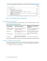
You can see if you are using HP DSM for MPIO in the CMC by selecting a server in a management
group, then clicking the Volumes and Snapshots tab. The Gateway Connection column shows multiple
connections labeled as DSM.

When accessing volumes from a server using HP DSM for MPIO, keep in mind the following:

HP DSM for MPIO and the Microsoft MPIO must be installed on the server.

With these installed, servers automatically use HP DSM for MPIO when you log on to volumes
from the iSCSI initiator.

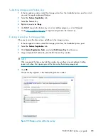
If you have dual storage NICs in your server, you can select the Enable multi-path option when
logging on to the volume, and log on from each NIC.

iSCSI and the HP P4000 SAN Solution

304

Summary of Contents for StorageWorks P4000 Series

Page 1: ... the HP StorageWorks SAN Solution It includes hardware configuration and information about designing and implementing a P4000 SAN The intended audience is system administrators responsible for implementing maintaining and managing a P4000 SAN Solution Part Number AX696 96036 Fourth edition November 2010 ...

Page 2: ...U S Government under vendor s standard commercial license The information contained herein is subject to change without notice The only warranties for HP products and services are set forth in the express warranty statements accompanying such products and services Nothing herein should be construed as constituting an additional warranty HP shall not be liable for technical or editorial errors or o...

Page 3: ... 33 Finding the storage systems 33 Configuring storage systems 34 Configure storage system categories 34 Creating a volume using the wizard 34 Enabling server access to volumes 35 Finding storage systems on an ongoing basis 36 Turn off Auto Discover by Broadcast for storage systems 36 Troubleshooting Storage systems not found 36 Possible reasons for not finding storage systems 36 Changing which st...

Page 4: ... of dedicated boot devices 50 Checking boot device status 50 Getting there 50 Replacing a dedicated boot device 51 3 Storage Configuration Disk RAID and Disk Management 53 Configuring RAID and managing disks 53 Getting there 53 Status indicators 53 Configuring and managing RAID 54 RAID Levels 54 Explaining RAID devices in the RAID setup report 55 RAID devices by RAID type 56 Virtual RAID devices 5...

Page 5: ...striping 74 Replacing a disk in a non hot swap storage system IBM x3650 74 Manually power off the disk in the CMC for RAID 1 RAID 10 and RAID 5 75 Physically replace the disk drive in the storage system 75 Manually powering on the disk in the CMC 75 RAID rebuilding 76 Replacing a disk in a hot swap storage system 76 Replace the disk 76 Physically replace the disk drive in the storage system 76 RAI...

Page 6: ...er 95 Example network cabling topologies with Adaptive Load Balancing 95 Creating a NIC bond 96 Prerequisites 96 Bond guidelines 96 Creating the bond 97 Verify communication setting for new bond 99 Viewing the status of a NIC bond 99 Deleting a NIC bond 101 Verify NIC settings and communication settings after deleting a bond 102 Disabling a network interface 102 Disabling a network interface 103 I...

Page 7: ...strative groups 117 Adding administrative groups 117 Editing administrative groups 118 Change the description of a group 118 Changing administrative group permissions 118 Adding users to an existing group 119 Removing users from a group 119 Deleting administrative groups 119 7 Monitoring and reporting 121 Alarms and events overview 121 Working with alarms 123 Filtering the alarms list 123 Displayi...

Page 8: ...rmation report details 139 Using hardware information log files 141 Saving log files 141 Using remote log files 142 Adding a remote log 142 Configuring the remote log target computer 142 Editing remote log targets 143 Deleting remote logs 143 System Summary 143 Exporting support logs 144 8 Working with management groups 145 Functions of management groups 145 Guide for management groups 145 Creatin...

Page 9: ...andwidth priority 160 Backing up a management group configuration 160 Backing up a management group with remote copy relationships 160 Back up a management group configuration 160 Restoring a management group 161 Safely shutting down a management group 161 Prerequisites 161 Shut down the management group 161 If volumes are still connected to servers or hosts 161 Start the management group back up ...

Page 10: ...Starting a virtual manager to regain quorum 174 Starting a virtual manager 175 Verifying virtual manager status 176 Stopping a virtual manager 176 Removing a virtual manager 176 10 Working with clusters 177 Clusters and storage system capacity 177 Prerequisites 177 Creating additional clusters 177 Prerequisites 177 Number of storage systems in clusters 177 To create additional clusters 177 Configu...

Page 11: ... snapshots 197 Schedules to snapshot a volume and capacity 197 Deleting snapshots 197 Ongoing capacity management 198 Number of volumes and snapshots 198 Reviewing SAN capacity and usage 198 Cluster use summary 198 Volume use summary 200 System Use summary 201 Measuring disk capacity and volume size 202 Block systems and file systems 202 Storing file system data on a block system 202 Changing the ...

Page 12: ...plication managed snapshot available 218 Making an application managed snapshot available on a stand alone server 219 Making an application managed snapshot available on a server in a Microsoft cluster 220 Managing snapshot temporary space 221 Convert the temporary space 221 Delete the temporary space 221 Creating a schedule to snapshot a volume 222 Best practices for scheduling snapshots of volum...

Page 13: ... SmartClone volumes 246 To create a SmartClone volume 246 Viewing SmartClone volumes 248 Map view 248 Using views 249 Viewing clone points volumes and snapshots 250 Editing SmartClone volumes 251 To edit the SmartClone volumes 252 Deleting SmartClone volumes 252 Deleting the clone point 253 Deleting multiple SmartClone volumes 253 15 Working with scripting 255 Scripting documentation 255 16 Contro...

Page 14: ...r SAN improvements 272 Network utilization to determine if NIC bonding could improve performance example 273 Load comparison of two clusters example 273 Load comparison of two volumes example 274 Accessing and understanding the Performance Monitor window 275 Performance Monitor toolbar 276 Performance monitor graph 277 Performance monitor table 277 Understanding the performance statistics 278 Moni...

Page 15: ... 297 Saving your customer information 297 19 iSCSI and the HP P4000 SAN Solution 299 Number of iSCSI sessions 299 Virtual IP addresses 299 Requirements for using a virtual IP address 299 iSNS server 300 iSCSI load balancing 300 Requirements 300 Compliant iSCSI initiators 300 Authentication CHAP 300 Requirements for configuring CHAP 301 iSCSI and CHAP terminology 302 Sample iSCSI configurations 302...

Page 16: ...rify storage system not running a manager 316 Stopping a manager 316 Repair the storage system 316 Prerequisite 316 Replace the disk 317 In IBM x3650 317 In the DL320s NSM 2120 Dell 2950 NSM 2060 NSM 4150 HP LeftHand P4500 HP LeftHand P4300 318 Rebuilding data 318 Recreate the RAID array 318 Checking progress for RAID array to rebuild 318 Return storage system to cluster 319 Restarting a manager 3...

Page 17: ...b in the IBM x3650 65 15 Arrangement of drives in the IBM x3650 65 16 Viewing the disk status of a VSA 65 17 Viewing the Disk Setup tab in a Dell 2950 or NSM 2060 66 18 Drive bays with bezel on in a Dell 2950 or NSM 2060 66 19 Drive bays with bezel off in a Dell 2950 or NSM 2060 66 20 Viewing the Disk Setup tab in a NSM 4150 67 21 Drive bays with bezel on in an NSM 4150 67 22 Drive bays with bezel...

Page 18: ...44 Verifying interface used for SAN iQ communication 102 45 Selecting the SAN iQ software network interface and updating the list of managers 108 46 Viewing the list of manager IP addresses 109 47 Events node and its parts 122 48 Opening the hardware information window 138 49 Viewing the hardware information for a storage system 139 50 Failover Manager in the available systems pool 150 51 Virtual ...

Page 19: ...shared snapshots appear in the CMC 234 81 Duplicate names on duplicate datastores in ESX Server 236 82 Example of using a base name with 10 SmartClone volumes 238 83 Rename SmartClone volume from base name 239 84 Programming cluster with SmartClone volumes clone point and the source volume 240 85 Changing one SmartClone volume changes all related volumes and snapshots 241 86 SysAdm cluster now has...

Page 20: ...mes 274 110 Performance Monitor window and its parts 275 111 Performance Monitor toolbar 276 112 Performance Monitor graph 277 113 Performance Monitor table 277 114 Performance statistics and where they are measured 279 115 Add Statistics window 283 116 Icons indicating license status for advanced features 290 117 Storage system with a license key 293 118 Registering advanced features for a manage...

Page 21: ...rk interfaces on the storage system 85 18 Comparison of Active Passive link aggregation dynamic mode and Adaptive Load Balancing bonding 88 19 Bonded network interfaces 89 20 NIC status in Active Passive configuration 89 21 Example Active Passive failover scenario and corresponding NIC status 90 22 NIC status during failover with Active Passive 90 23 Link aggregation dynamic mode failover scenario...

Page 22: ...ly change rates 214 48 Requirements for scheduling snapshots 222 49 Characteristics for creating a schedule to snapshot a volume 223 50 Terms used for SmartClone features 233 51 Characteristics for new SmartClone volumes 237 52 Characteristics of SmartClone volumes 242 53 How it works clone point 243 54 How it works shared snapshots 245 55 Requirements for changing SmartClone volume characteristic...

Page 23: ...Identifying Ethernet interfaces on the storage system 307 69 Document conventions 312 70 Replacing the ghost storage system with the repaired storage system 320 71 P4000 SAN Solution user guide 23 ...

Page 24: ...24 ...

Page 25: ...and volumes Auto discover When you open the CMC the first time it automatically searches the subnet for storage systems Any storage systems it discovers appear in the navigation window on the left side of the CMC If no storage systems are found the Find Systems Wizard opens and takes you through the steps to discover the storage systems on your network Disable the Auto Discover by Broadcast featur...

Page 26: ...ement groups Events Servers Administration Sites Failover Managers and Virtual Managers Clusters Storage Systems and their configuration categories Volumes including SmartClones Snapshots Remote copies Tab window For each element selected in the navigation window the tab window on the right displays information about it Commands related to the element are accessible from the Tasks menu on the bott...

Page 27: ...systems in the Available Systems pool to access the configuration categories After you have created management groups you must manually log in to access the management group After you have logged in to one management group the CMC attempts to log in automatically to other management groups using the first login CAUTION Do not log in to the same management group from more than one CMC Traversing th...

Page 28: ...geographic location using the SAN iQ software feature Remote Copy SmartClone volumes SmartClones are space efficient copies of existing volumes or snapshots They appear as multiple volumes that share a common snapshot called a clone point and share this snapshot data on the SAN Icons Each item in the navigation window has an icon depicting what type of item it is A faded looking icon indicates a r...

Page 29: ...uster or deleting shared snapshots the Map View tab allows you to easily identify how many snapshots and volumes are affected by such changes Manipulating the Map View The window contains display tools to control and manipulate the view The display tools are available from the Map View Tasks menu or from the tool bar across the top of the window The tools function the same from either the tool bar...

Page 30: ...ion see Alarms and events overview on page 121 Setting preferences Use the Preferences window to set the following Font in the CMC Locale for the CMC Naming conventions for storage elements Online upgrade options see Setting upgrade preferences page 46 Setting the font and locale Use the Preferences window opened from the Help menu to set font and locale in the CMC Select the font that meets your ...

Page 31: ...tClone volumes Changing naming conventions Change the elements that use a default naming convention or change the naming convention itself Table 2 on page 31 illustrates the default naming conventions built into the SAN iQ software Table 2 Default names provided Default name Element None Management Groups None Clusters None Volumes VOL_ SmartClone Volumes _SS_ Snapshots _RS_ Remote Snapshots _Sch_...

Page 32: ...s work Example Default name Element VOL_VOL_ExchLogs_SS_3_1 VOL_ SmartClone Volumes VOL_ExchLogs_SS_1 _SS_ Snapshots VOL_RemoteBackup_RS_1 _RS_ Remote Snapshots VOL_ExchLogs_Sch_SS_2 1 _Sch_SS_ Schedules to Snapshot a Volume VOL_ExchLogs_Sch_RS_2_Pri 1 VOL_Remote Backup_Sch_RS_1_Rmt 1 _Sch_RS_ Schedules to Remote Snapshot a Volume This example is illustrated in Figure 3 on page 32 Figure 3 Using t...

Page 33: ...ethods to create storage as well as detailed information on features of the iSCSI SAN Prerequisites Install the storage systems on your network Know the IP address or host name you configured with the KVM or serial Configuration Interface when you installed the storage system Install the HP StorageWorks P4000 CMC software on a management workstation or server that can connect to the storage system...

Page 34: ...gories 1 From the navigation window select a storage system in the Available Systems pool 2 Double click to open the tree underneath the storage system 3 Select the Storage category 4 Select the RAID Setup tab and verify the RAID settings or change the RAID level 5 In the list of configuration categories select the TCP IP Network category and configure the network settings Creating a volume using ...

Page 35: ...er VIP to use for the cluster A name for the volume The size of the volume Enabling server access to volumes Use the Assign Volume and Snapshot wizard to prepare the volume for server access You set up application servers in the management group then assign volumes to the servers See Chapter 16 on page 257 for a complete discussion of these functions To work through the Assign Volume and Snapshot ...

Page 36: ...or vice versa 3 If searching again does not work try the following Check the physical connection of the storage system Wait a few minutes and try the search again If activity to the storage system was frequent the storage system might not have responded to the search Possible reasons for not finding storage systems Other problems can occur that prevent CMC from finding a storage system Extremely h...

Page 37: ...e below lists the CMC setup required for remote support Table 5 CMC setup for remote support For more information see Requirement Enabling SNMP agents on page 130 SNMP enabled on each storage system Adding SNMP traps on page 133 SNMP trap recipient set to IP address of the system where the remote support client is installed Your network administrator Port 8959 used for the CLI open Adding a new ad...

Page 38: ...Getting started 38 ...

Page 39: ...nitions Diagnostics Use the hardware category to run hardware diagnostic tests to view current hardware status and configuration information and to save log files Storage Manage RAID and the individual disks in the storage system TCP IP Network For each storage system configure and manage the network settings including network interface cards NICs the routing table and which interface carries SAN ...

Page 40: ...ystems in the management group and log back in to them individually Automatic login Once you have logged in to a management group additional log ins are automatic if the same user names and passwords are assigned If management groups have different user names or passwords then the automatic log in fails In that case you must log in manually 1 Type the correct user name and password 2 Click Log In ...

Page 41: ...e for use in case of a storage system failure When you back up a storage system configuration the configuration information about the storage system is stored in a file If a storage system failure occurs restore the backed up configuration to a replacement storage system The replacement storage system will be configured identically to the original storage system at the time it was backed up NOTE B...

Page 42: ...em 2 Click Storage System Tasks on the Details tab and select Back Up or Restore 3 Click Back Up 4 Navigate to a folder to contain the storage system configuration backup file 5 Enter a meaningful name for the backup file or accept the default name Storage System_Configuration_Backup NOTE The configuration files for all storage systems that you back up are stored in the location you choose If you ...

Page 43: ...stics as described in Manual configuration steps following the restore on page 42 RAID Network routes IP address Powering off or rebooting the storage system You can reboot or power off the storage system from the CMC You can also set the amount of time before the process begins to ensure that all activity to the storage system has stopped Powering off the storage system through the CMC physically...

Page 44: ...45 2 Manually power off the disk enclosure When you reboot the storage system use the CMC as described in Rebooting the storage system on page 44 This process reboots only the server blades enclosure or the system controller Rebooting the storage system 1 Select a storage system in the navigation window and log in 2 Click Storage System Tasks on the Details tab and select Power Off or Reboot 3 In ...

Page 45: ... The button changes to Power Off 4 In the minutes field type the number of minutes before the powering off should begin Enter any whole number greater than or equal to 0 If you enter 0 the storage system powers off shortly after you complete Step 5 NOTE If you enter 0 for the value when powering off you cannot cancel the action Any value greater than 0 allows you to cancel before the power off act...

Page 46: ...om the Help menu control the settings described in Table 6 on page 46 Table 6 Upgrade preferences Options Preference Automatic System automatically downloads upgrade files when they become available On Request Default When upgrades are available you must click Start Download from the Upgrades tab to download upgrade files Download Fast Uses available bandwidth for file downloads Normal Default Red...

Page 47: ... change the download directory see Setting upgrade preferences on page 46 If you decide not to install some upgrades now the next time you check for upgrades the system will not download files you already have 3 Continue with the upgrading process To upgrade the CMC see Upgrading the CMC on page 47 To upgrade storage systems in a management group or available systems see Upgrading storage systems ...

Page 48: ... or patch you want to install and click OK The Package Selection window opens if you have your Upgrade Select Mode set to Advanced See Setting upgrade preferences on page 46 The Install Action Required window opens with a list of software that must be upgraded before continuing with the SAN iQ upgrade The current versions were downloaded to your download directory 3 If you are using the listed sof...

Page 49: ...lation Failed to view more information about the failure To save the upgrade summary information click Export Information Registering advanced features for a storage system Using the Feature Registration tab register individual storage systems for advanced features For more information about registering advanced features see Chapter 18 on page 289 Determining volume and snapshot availability The A...

Page 50: ...If necessary compact flash cards can be deactivated or activated using the buttons on this tab However you should only take action on these cards if instructed by HP Technical Support Checking boot device status View dedicated boot device status in the Boot Devices tab window in the Storage category in the storage system tree Getting there 1 Select a storage system in the navigation window and log...

Page 51: ...t been used in a storage system It is ready to be activ ated Unformatted The device is not recognized as a boot device Not Recognized The device cannot be used For example the compact flash card is the wrong size or type Unsupported NOTE When the status of a boot device changes an event is generated See Alarms and events overview on page 121 Replacing a dedicated boot device If a boot hard drive f...

Page 52: ...Working with storage systems 52 ...

Page 53: ...s Getting there 1 In the navigation window select a storage system and log in if necessary 2 Open the tree under the storage system and select the Storage category Figure 9 Viewing the storage configuration category for a storage system Columns in the RAID Setup tab show four categories Device Name Device Type or the RAID level Device Status Subdevices Status indicators On the RAID Setup tab and t...

Page 54: ...you will experience data loss if a hard drive that holds the data fails However because no logical drive capacity is used for redundant data this method offers the best capacity This method offers the best processing speed by reading two stripes on different hard drives at the same time and by not having a parity drive RAID 0 Strip ing No Fault Tolerance Offers a good combination of data protectio...

Page 55: ...e controller uses the parity data and the data on the remaining drives to reconstruct data from the failed drive The system continues operating with a slightly reduced perform ance until you replace the failed drive RAID 5 can only withstand the loss of one drive without total array failure It requires an array with a minimum of three physical drives Usable capacity is N 1 where N is the number of...

Page 56: ... you first configured the data disk in the VI Client HP recommends installing VMware ESX Server on top of a server with a RAID 5 or RAID 6 configuration Planning the RAID configuration The RAID configuration you choose for the storage system depends on your plans for data fault tolerance data availability and capacity growth CAUTION Plan your RAID configuration carefully After you have configured ...

Page 57: ...be obtained from the other storage systems Using disk RAID with Network RAID in a cluster Always use Network RAID in a cluster to protect volumes across storage systems The redundancy provided by RAID 10 RAID 5 RAID 50 or RAID 6 ensures availability at the storage system level Using Network RAID for volumes in a cluster ensures availability at the cluster level For example Using Network RAID up to...

Page 58: ...torage systems RAID 6 Yes Yes However if any disk in the storage system fails the entire storage system must be copied from another storage system in the cluster Volumes configured with Network RAID 10 or greater on clustered storage sys tems RAID 0 Yes Yes 1 disk per RAID set can fail without copying from another storage system in the cluster Volumes configured with Network RAID 10 or greater on ...

Page 59: ... following guidelines when deciding where to set the RAID rebuild rate Setting the rate high is preferred for rebuilding RAID quickly and protecting data However it slows down user access to data Setting the rate low allows users quicker access to data during the rebuild but slows the rebuild rate CAUTION In the IBM x3650 the RAID rebuild rate cannot be changed from high This setting may affect th...

Page 60: ... take several hours for the disks to synchronize in a RAID 10 RAID 5 RAID 50 or RAID 6 configuration During this time performance will be degraded When the RAID status on the RAID Setup tab shows Normal the disks provide fully operational data redundancy and performance returns to normal Monitoring RAID status RAID is critical to the operation of the storage system If RAID has not been configured ...

Page 61: ...in the navigation window 1 RAID status Figure 11 Monitoring RAID status on the main CMC window The status displays one of four RAID states Normal RAID is synchronized and running No action is required Rebuilding A new disk has been inserted in a drive bay or a hot spare has been activated and RAID is currently rebuilding No action is required Degraded RAID is degraded A disk may have failed or hav...

Page 62: ...isk Getting there 1 In the navigation window select a storage system 2 Select the Storage category in the tree below it 3 Select the Disk Setup tab Reading the disk report on the Disk Setup tab The Disk Setup tab provides a status report of the individual disks in a storage system Figure 12 shows the Disk Setup tab and Table 14 on page 63 describes the corresponding disk report Figure 12 Example o...

Page 63: ...sk Model The serial number of the disk Serial Number The class type of disk for example SATA 3 0 GB Class The data storage capacity of the disk Capacity Verifying disk status Check the Disk Setup window to determine the status of disks and to take appropriate action on individual disks when preparing to replace them Viewing disk status for the DL320s NSM 2120 The disks are labeled 1 through 12 in ...

Page 64: ...n the Disk Setup window Figure 15 on page 65 and correspond to the disk drives labeled 0 through 5 from left to right top to bottom when you are looking at the front of the IBM x3650 Figure 16 on page 65 For the IBM x3650 the columns Health and Safe to Remove help assess the health of a disk and tell you whether you can replace it without losing data Storage Configuration Disk RAID and Disk Manage...

Page 65: ... disk status for the VSA For the VSA the Disk Setup window shows 1 virtual disk Figure 17 Viewing the disk status of a VSA NOTE To change the size of the data disk in a VSA see the HP StorageWorks P4000 VSA User Manual for instructions about recreating the disk in the VI Client P4000 SAN Solution user guide 65 ...

Page 66: ...it without losing data Figure 18 Viewing the Disk Setup tab in a Dell 2950 or NSM 2060 Figure 19 Drive bays with bezel on in a Dell 2950 or NSM 2060 Figure 20 Drive bays with bezel off in a Dell 2950 or NSM 2060 Viewing disk status for the NSM 4150 The disks are labeled 0 through 14 in the Disk Setup window and correspond to the disk drives from left to right when you are looking at the front of t...

Page 67: ...Figure 24 on page 68 and correspond to the disk drives from left to right 1 4 7 10 on the top row and 2 5 8 11 on the second row and so on as shown in Figure 25 on page 68 when you are looking at the front of the HP LeftHand P4500 and HP StorageWorks P4500 G2 For the HP LeftHand P4500 and HP StorageWorks P4500 G2 the columns Health and Safe to Remove help you assess the health of a disk and tell y...

Page 68: ...k Setup window Figure 26 on page 69 and correspond to the disk drives from left to right 1 3 5 and 7 on the top row and 2 4 6 and 8 on the second row as shown in Figure 27 on page 69 when you are looking at the front of the HP LeftHand P4300 and HP StorageWorks P4300 G2 For the P4300 and the P4300 G2 the columns Health and Safe to Remove help you assess the health of a disk and tell you whether or...

Page 69: ... HP LeftHand P4800 and HP StorageWorks P4800 G2 The disks are labeled 1 through 35 in the Disk Setup window Figure 28 on page 70 and correspond to the disk drives from left to right 1 8 15 22 on the top row and 2 9 16 23 30 on the second row and so on as shown in Figure 29 on page 70 when you are looking at the front of the HP LeftHand P4800 and HP StorageWorks P4800 G2 P4000 SAN Solution user gui...

Page 70: ...em depends upon a number of factors including the RAID configuration the data protection level of volumes and snapshots and the number of disks being replaced Replacing a disk in a storage system that is in a cluster requires rebuilding data either just on the replaced disk or in the case of RAID 0 on the entire storage system Replacing a disk in a storage system includes the following basic steps...

Page 71: ...onal information about preparing for disk replacement is included in the following sections below Preparing for a disk replacement Best practice checklist for single disk replacement in RAID 0 Best practice checklist for single disk replacement in RAID 1 RAID 10 RAID 5 RAID 50 and RAID 6 Using Repair Storage System Repair Storage System is a procedure that allows you to replace a disk and trigger ...

Page 72: ...nditions You know which disk needs to be replaced through SAN iQ monitoring When viewed in the Disk Setup tab the Drive Health column shows Marginal replace as soon as possible or Faulty replace right away RAID is still on though it may be degraded and a drive is inactive Use the instructions in Replacing disks appendix on page 315 for these situations If RAID is off If you are unsure which disk t...

Page 73: ...er does not have enough space for changing the Network RAID level take a backup of the volumes or snapshots and then delete them from the cluster After the disk replacement is complete you can recreate the volumes and restore the data from the backup All volumes and snapshots show a status of Normal Any volumes or snapshots that are being deleted have finished deleting Use the instructions in Repl...

Page 74: ...a missing disk in a storage system Figure 30 Viewing a power off or missing disk 1 In the navigation window select the storage system with the replaced drive 2 Select the Storage category in the navigation tree 3 Click the Disk Setup tab 4 Select the disk in the list to power on 5 Click Disk Setup Tasks and select Power On Disk 6 Click OK on the confirmation message Volume restriping After the dis...

Page 75: ...res the disk replacement 2 Select the Storage category 3 Select the Disk Setup tab 4 Select the disk in the list to power off 5 Click Disk Setup Tasks and select Power Off Disk 6 Click OK on the confirmation message Physically replace the disk drive in the storage system See the hardware documentation for the storage system Manually powering on the disk in the CMC After inserting the new disk into...

Page 76: ...P4300 and P4500 HP StorageWorks P4500 G2 and P4500 G2 HP StorageWorks P4700 HP StorageWorks P4800 Complete the checklist for replacing a disk in RAID 1 RAID 10 RAID 5 RAID 50 or RAID 6 Then follow the appropriate procedures for the storage system CAUTION Always use a new drive when replacing a disk in a Dell 2950 NSM 2060 or NSM 4150 Never reinsert the same drive or another drive from the same Del...

Page 77: ... replaced disk There may be a delay of up to a couple of minutes before you can see that RAID is rebuilding on the RAID Setup or Disk Setup tabs Figure 32 RAID rebuilding on the RAID Setup tab Figure 33 Disk rebuilding on the Disk Setup tab P4000 SAN Solution user guide 77 ...

Page 78: ...Storage Configuration Disk RAID and Disk Management 78 ...

Page 79: ...cluster Use static IP addresses or reserved addresses if using DHCP Configure storage system settings for speed and duplex frame size and flow control BEFORE bonding NICs and before putting the storage system into a management group and cluster If adding a second IP address to a storage system the second IP address must be on a separate subnet If the two IP addresses are on the same subnet they mu...

Page 80: ...g there 1 In the navigation window select a storage system 2 Open the tree under the storage system and select TCP IP Network Figure 34 Viewing the TCP IP Network category for a storage system Managing settings on network interfaces Configure or change the settings of the network interfaces in the storage systems See Network best practices on page 79 for more information Requirements These setting...

Page 81: ...ace See Table 21 on page 89 for a detailed de scription of individual NIC status Status Lists the frame size setting for the device Frame Size For Active Passive bonds Indicates whether the device is set as preferred The preferred interface is the interface within an Active Passive bond that is used for data transfer during normal operation Preferred Changing speed and duplex settings The settings...

Page 82: ...want to edit 5 Click TCP IP Status Tasks and select Edit 6 Select the combination of speed and duplex that you want 7 Click OK A series of status messages appears Then the changed setting appears in the TCP status report NOTE You can also use the Configuration Interface to edit the TCP speed and duplex See Setting the TCP speed duplex and frame size on page 308 Changing NIC frame size Configure or...

Page 83: ...ze on all storage systems on the network and set compatible frame sizes on all clients that access the storage systems Consult with your network administrator for recommended storage system frame sizes and the corresponding frame sizes in bytes for Windows and Linux clients in your environment Jumbo frames Frame sizes that are greater than 1500 bytes are called jumbo frames Jumbo frames must be su...

Page 84: ...figured before creating NIC bonds All NICs should have or must have if they are bonded the same flow control settings Flow control cannot be changed when the port is disabled Enabling NIC flow control To enable NIC flow control 1 In the navigation window select a storage system and log in 2 Open the tree and select the TCP IP Network category 3 Select the TCP Status tab 4 Select the interface you ...

Page 85: ...t interfaces Label Where labeled eth0 eth1 Motherboard Port0 Motherboard Port1 G4 Motherboard Port1 G4 Motherboard Port2 Motherboard Port1 Motherboard Port2 For bonded interfaces BondN or Bond0 In the TCP IP Network configuration category in the CMC TCP IP tab TCP Status tab Intel Gigabit Ethernet Broadcom Gigabit Ethernet In the Configuration Interface available through the storage system s seria...

Page 86: ...Click Edit 5 Select IP address and complete the fields for IP address Subnet mask and Default gateway 6 Click OK 7 Click OK on the confirmation message 8 Click OK on the message notifying you of the automatic log out NOTE Wait a few moments for the IP address change to take effect 9 Log in to the newly addressed storage system Using DHCP A DHCP server becomes a single point of failure in your syst...

Page 87: ...es both load balancing and localized fault tolerance NOTE The VSA does not support NIC bonding Depending on your storage system hardware network infrastructure design and Ethernet switch capabilities you can bond NICs in one of three ways Active Passive You specify a preferred NIC for the bonded logical interface to use If the preferred NIC fails then the logical interface begins using another NIC...

Page 88: ...e DHCP for the bond IP NIC bonding and speed duplex frame size and flow control settings These settings are controlled on the TCP Status tab of the TCP IP Network configuration category If you change these settings you must ensure that both sides of the NIC cable are configured in the same manner For example if the storage system is set for Auto Auto the switch must be set the same See TCP status ...

Page 89: ... longer has a link Passive Failed If the active NIC fails or if its link is broken due to a cable failure or a failure in a local device to which the NIC cable is connected then the status of the NIC becomes Passive Failed and the other NIC in the bond if it has a status of Passive Ready becomes active This configuration remains until the failed preferred interface is brought back online When the ...

Page 90: ...nk is restored Summary of NIC status during failover Table 23 on page 90 shows the states of Eth0 and Eth1 when configured for Active Passive Table 23 NIC status during failover with Active Passive Status of Eth1 Status of Eth0 Failover status Preferred No Status Passive Ready Data Transfer No Preferred Yes Status Active Data Transfer Yes Normal Operation Preferred No Status Active Data Transfer Y...

Page 91: ...topology with server failover The two switch scenario in Figure 35 on page 91 is a basic yet effective method for ensuring high availability If either switch fails or a cable or NIC on one of the storage systems fails the Active Passive bond causes the secondary connection to become active and take over P4000 SAN Solution user guide 91 ...

Page 92: ... data transfer Both interfaces have an active status If the interface link to one NIC goes offline the other interface continues operating Using both NICs also increases network bandwidth Requirements for link aggregation dynamic mode To configure Link Aggregation Dynamic Mode Both NICs should be enabled NICs must be configured to the same subnet NICs must be connected to a single switch that is L...

Page 93: ...ive Eth1 is Active 1 Link Aggregation Dynamic Mode bond0 is created Eth0 and Eth1 are both active Eth0 status becomes Passive Failed Eth1 status remains Active 2 Eth0 interface fails Because Link Aggregation Dynamic Mode is configured Eth1 continues operating Eth0 resumes Active status Eth1 remains Active 3 Eth0 link failure is repaired Summary of NIC states during failover Table 25 on page 93 sho...

Page 94: ... both interfaces simultaneously for data transfer Both interfaces have an active status If the interface link to one NIC goes offline the other interface continues operating Using both NICs also increases network bandwidth Requirements for Adaptive Load Balancing To configure Adaptive Load Balancing Both NICs must be enabled NICs must be configured to the same subnet NICs can be connected to separ...

Page 95: ...fails Because Adaptive Load Balancing is configured Motherboard Port2 con tinues operating Motherboard Port1 resumes Active status Motherboard Port2 remains Active 3 Motherboard Port1 link failure is repaired Summary of NIC states during failover Table 27 on page 95 shows the states of Motherboard Port1 and Motherboard Port2 when configured for Adaptive Load Balancing Table 27 NIC status during fa...

Page 96: ...ces on page 80 Bond guidelines Create a bond on a storage system before you add the storage system to a management group Create bonds of two interfaces An interface can only be in one bond Record the configuration information of each interface before you create the bond Then if you delete the bond you can return to the original configuration if desired When you delete an Active Passive bond the pr...

Page 97: ...work correctly you might Lose the storage system from the network Lose quorum in the management group for a while See Deleting a NIC bond on page 308 for information about deleting NIC bonds using the Configuration Interface Creating the bond 1 Log in to the storage system 2 Select the TCP IP category from the tree 3 On the TCP IP tab select both NICs to bond 4 Click TCP IP Tasks and select New Bo...

Page 98: ...n take a few minutes for the storage system to re initialize the search may fail the first time If the search fails wait a minute or two and choose Try Again on the Network Search Failed message 12 Verify the new bond interface 1 Bonded logical network interface 2 Physical interfaces shown as slaves Figure 40 Viewing a new Active Passive bond The bond interface shows as bond0 and has a static IP a...

Page 99: ...rface used for SAN iQ communication 3 Verify that the SAN iQ communication port is correct Viewing the status of a NIC bond You can view the status of the interfaces on the TCP Status tab Notice that in the Active Passive bond one of the NICs is the preferred NIC In both the Link Aggregation Dynamic Mode bond and the Adaptive Load Balancing bond neither physical interface is preferred Figure 42 on...

Page 100: ... Preferred interface Figure 42 Viewing the status of an Active Passive bond 1 Neither interface is preferred Figure 43 Viewing the status of a link aggregation dynamic mode bond Managing the network 100 ...

Page 101: ...bled and its IP address is set to 0 0 0 0 When you delete either a Link Aggregation Dynamic Mode or an Adaptive Load Balancing bond one of the active interfaces in the bond retains the IP address of the deleted logical interface The other NIC is disabled and its IP address is set to 0 0 0 0 1 Log in to the storage system and expand the tree 2 Select the TCP IP category from the tree 3 On the TCP I...

Page 102: ...d 1 Select a storage system and open the tree below it 2 Select the TCP IP Network category 3 Check the interfaces on the TCP IP tab and reconfigure them if necessary After deleting a bond the interfaces may not have the correct IP addresses or one interface may be disabled 4 Click the Communication tab Figure 45 Verifying interface used for SAN iQ communication 5 Verify that the SAN iQ communicat...

Page 103: ...ent group a window opens which displays all the IP addresses of the managers in the management group and a reminder to reconfigure the application servers that are affected by the update Configuring a disabled interface If one interface is still connected to the storage system but another interface is disconnected you can reconnect to the second interface using the CMC See Configuring the IP addre...

Page 104: ...o use DHCP and then change the configuration to use a static IP address the DNS server provided by DHCP will remain on the DNS tab You can remove or change this DNS server Getting there 1 In the navigation window select a management group and log in 2 Select the DNS tab Adding the DNS domain name Add the name of the DNS domain in which the management group resides 1 Click DNS Tasks and select Edit...

Page 105: ...Select the server to edit 4 Click DNS Tasks and select Edit DNS Servers 5 Select the server again and click Edit 6 Type the new IP address for the DNS server and click OK Editing a domain name in the DNS suffixes list Change a domain name of a management group 1 In the navigation window select a management group and log in 2 Select the DNS tab 3 Click DNS Tasks and select Edit DNS Domain Name 4 En...

Page 106: ...manually on page 86 Information for each route listed includes the device the network gateway mask and flags Adding routing information 1 In the navigation window select a storage system and log in 2 Open the tree and select the TCP IP Network category 3 Select the Routing tab 4 Click Routing Tasks and select Edit Routing Information 5 Click Add 6 Select the port to use for routing in the Device l...

Page 107: ... the storage system to communicate with other storage systems on the network and to update the list of managers that the storage system can communicate with Selecting the interface used by the SAN iQ software The SAN iQ software uses one network interface for communication with other storage systems on the network In order for clustering to work correctly the SAN iQ software communication interfac...

Page 108: ...g the list of manager IP addresses Update the list of manager IP addresses to ensure that a manager running on this storage system is communicating correctly with all managers in the management group Requirements Each time you update the list of managers you must reconfigure application servers that use the management group to which this storage system belongs Only update the list mode if you have...

Page 109: ...List The list is updated with the current storage system in the management group and a list of IPs with every manager s enabled network interfaces A window opens which displays the manager IP addresses in the management group and a reminder to reconfigure the application servers that are affected by the update P4000 SAN Solution user guide 109 ...

Page 110: ...Managing the network 110 ...

Page 111: ...es the GMT time zone whether or not you use NTP Setting date and time Set the date and time on the management group s if not using an NTP time service Management group time When you create a management group you set the time zone and the date and time while going through the Management Groups Clusters and Volumes wizard This ensures that all the storage systems in the management group have the sam...

Page 112: ...l network would have a reliable and fast connection to the storage system Not preferred designates an NTP server to be used as a backup if a preferred NTP server is not available An NTP server that is not preferred might be one that is located elsewhere or has a less reliable connection 4 Click OK The NTP server is added to the list on the NTP tab The NTP servers are accessed in the order you add ...

Page 113: ...der of access for time servers 1 Delete the server whose place in the list you want to change 2 Add that same server back into the list It is placed at the bottom of the list and is the last to be accessed Editing the date and time You initially set the date and time when you create the management group using the Management Groups Clusters and Volumes wizard If necessary you can edit these setting...

Page 114: ...me zone later if necessary If you do not set the time zone for each management group the management group uses GMT whether or not you use NTP Files display the time stamp according to this local time zone 1 Click Time Tasks and select Edit Time Zone 2 From the drop down list select the time zone in which this management group resides 3 Click OK Note the change in the Time column of the Time tab wi...

Page 115: ...s a member of the Full Administrator group by default Adding a new administrative user Add administrative users as necessary to provide access to the management functions of the SAN iQ software 1 Log in to the management group and select the Administration node 2 Click Administration Tasks in the tab window and select New User 3 Type a User Name and Description 4 Type a password and confirm that p...

Page 116: ...Administration Tasks in the tab window and select Edit User 4 Click Add in the Member Groups section 5 Select the groups to which to add the new user 6 Click OK 7 Click OK to finish editing the administrative user Removing group membership from a user 1 Log in to the management group and select the Administration node 2 Select a user in the Users table 3 Click Administration Tasks in the tab windo...

Page 117: ...gned to group Name of group Manage all functions read write access to all func tions Full_Administrator View only capability to all functions read only View_Only_Administrator Administrative groups can have Different levels of access to the storage system such as read write Access to different management capabilities for the SAN such as configuring network capabilities Adding administrative groups...

Page 118: ...nformation about these functions Read Modify User can view and modify existing settings for these functions Full User can perform all actions view modify add new delete in all functions 1 Add a user to the group Click Add in the Users section Select one or more users to add to the group Click Add 2 Click OK to finish creating a new group Editing administrative groups Each management group has an a...

Page 119: ...ct the Administration node 2 Click Administration Tasks in the tab window and select Edit Group 3 Click Add in the Users section The Add Users window opens with a list of administrative users 4 Select one or more users to add to the group 5 Click Add 6 Click OK to finish creating a new group Removing users from a group 1 Log in to the management group and select the Administration node 2 Click Adm...

Page 120: ...Administrative users and groups 120 ...

Page 121: ...their severity Informational Provides status information about user activities such as creating a volume and system actions and status such as a storage system is up These types of events do not require you to take action and are available only from the Events node for each management group Warning Provides important information about a system component that may require you to take action These ty...

Page 122: ... for storage systems listed under Available Systems in the CMC because the systems are not currently in use Table 30 defines the alarms and events columns that you see in the CMC Table 30 Alarms and events column descriptions Description Column Severity of the event informational warning or critical Severity Date and time the event occurred Date Time Identification number and name of event Event B...

Page 123: ...list of alarms Double click an alarm to see more details For definitions of the event types and columns see Alarms and events overview on page 121 NOTE You should review alarms regularly especially the critical ones and take the appropriate action to resolve the alarm Alarms stay in the Alarms window until the situation is resolved A warning or critical icon also appears in the navigation window t...

Page 124: ...e details to the clipboard 6 Click Close to close the Alarm details window Displaying alarms in a separate window You can display the alarms in a separate window that you can resize and move to a convenient location on your screen To display alarms in a separate window 1 In the navigation window log in to the management group 2 In the Alarms window click Alarm Tasks and select Open Alarms in Windo...

Page 125: ...a management group New appears next to the Events node to let you know there are new events To display new events 1 When New appears next to the Events node click New Events on the toolbar to bring in the newest events 2 Sort by the Date Time column to display the newest events Filtering the events list You can filter events listed in the Events node the following ways Using the Filters drop down ...

Page 126: ...ons from more than one filter list the system does an and so that all of the selected options must apply to an event for the event to stay in the Events list 5 Click Apply The events list is filtered based on your selections To remove the filters and view all events click Clear Saving filter views Save filter views for later use Custom filters appear in the Filters drop down list in the toolbar be...

Page 127: ... email message click Copy to copy the details to the clipboard 7 Click Close to close the Event Details window Displaying events in a separate window You can display the events in a separate window that you can resize and move to a convenient location on your screen To display events in a separate window 1 In the navigation window log in to the management group 2 Select Events in the tree 3 Click ...

Page 128: ...nation computer The syslog facility to use is local5 and the syslog levels are LOG_INFO LOG_WARNING LOG_CRIT See the syslog documentation for information about configuring syslog To set up remote log destinations 1 In the navigation window log in to the management group 2 Select Events in the tree 3 Click Event Tasks and select Edit Remote Log Destinations 4 In the Destinations field enter the IP ...

Page 129: ...ttings 4 In the Server IP Hostname field enter the IP address or host name of your email SMTP server 5 In the Server Port field enter the email port The standard port is 25 6 In the Sender Address field enter the email address including the domain name to use as the sender for notifications The system automatically adds the host name of the storage system in the email From field which appears in m...

Page 130: ... Installing the LeftHand Networks MIB on page 134 for a list of MIBs After installing SAN iQ version 9 0 the SNMP agent on the storage system will be enabled by default and allows read only access using the community string public You can change this configuration To receive notification of events you must configure SNMP traps If you are using the HP System Management Homepage you can view the SNM...

Page 131: ...s and the IP Netmask as None to allow a specific host to access SNMP or you can specify the Network Address with its netmask value so that all hosts matching that IP and netmask combination can access SNMP NOTE Use the CMC ping feature to verify IP addresses while configuring access control See Pinging an IP address on page 85 Adding an SNMP client 1 In the navigation window log in to the manageme...

Page 132: ...K on the Edit SNMP Settings window when you are finished Deleting access control entries 1 In the navigation window log in to the management group 2 In the tree select Events SNMP 3 Click SNMP Tasks and select Edit SNMP General Settings 4 Select a client listed in the Access Control list and click Delete A confirmation message opens 5 Click OK 6 Click OK on the Edit SNMP Settings window when you a...

Page 133: ...ote support 8 Click OK 9 Repeat Step 5 through Step 8 for each trap recipient 10 Click OK on the Edit SNMP Traps window when you are finished adding hosts Editing trap recipients 1 Log in to the storage system and expand the tree 2 In the navigation window log in to the management group 3 In the tree select Events SNMP 4 Click SNMP Tasks and select Edit SNMP Traps Settings 5 Select one of the Trap...

Page 134: ...uration DNS server configuration details and more NOTE With version 8 5 and later traps no longer all use a single OID The LEFTHAND NETWORKS NOTIFICATION MIB defines the OIDs now in use Installing the LeftHand Networks MIB The complete set of standard SNMP MIB files and the LeftHand Networks MIB files are installed when you install the CMC using the Complete option The installer places the MIBs in...

Page 135: ...B NOTIFICATION LOG MIB RFC1213 MIB SNMP TARGET MIB SNMP VIEW BASED ACM MIB SNMPv2 MIB UCD DLMOD MIB UCD SNMP MIB Using hardware information reports The Diagnostics category found in the tree under every storage system includes multiple types of information and reporting capabilities Review the Hardware Information report of system statistics hardware and configuration information Use the Diagnosti...

Page 136: ...required to run tests clear the check boxes for any tests that you do not need 4 Click Diagnostic Tasks and select Run Tests A progress message appears When the tests complete the results of each test appearin the Result column 5 Optional When the tests complete if you want to view a report of test results click Save to File Then select a location for the diagnostic report file and click Save The ...

Page 137: ... is normal and not charging or testing Checks the status of the battery backed up cache Cache BBU Status One or more drives are missing All disk drives are present Checks for the presence of all disk drives Disk Status Test The temperature is outside normal operating range The temperature is within normal operating range Checks the temperature of all disk drives Disk Temperature Test Warning or Fa...

Page 138: ...ware information reports display statistics about the performance of the storage system its drives and configuration Statistics in the hardware reports are point in time data gathered when you click the Refresh button on the Hardware Information tab Generating a hardware information report To generate a Hardware Information report 1 Select the Hardware Information tab 1 Link to obtain hardware sta...

Page 139: ... the report 3 Click Save The report is saved with an html extension Hardware information report details This section contains more information about selected details of the Hardware Information report NOTE Available hardware report statistics vary depending on the storage system Table 32 Selected details of the hardware report means this This term Hostname of the storage system Hostname Full versi...

Page 140: ...e size CPU Information about the CPU CPU seconds shows the number of CPU seconds spent on user tasks kernel tasks and in idle state Machine uptime is the total time the storage system has been running from initial boot up Stat Selected information about the backplane LEDs LED support and id LED Backplane information Includes chassis serial number and BIOS version Motherboard information For each d...

Page 141: ... computer This way if the storage system goes off line the log files will be available This section explains how to save a hardware information log file to a txt file on the local storage system or a remote computer See these sections Saving log files on page 141 Using remote log files on page 142 Saving log files If Technical Support requests that you send a copy of a log file use the Log Files t...

Page 142: ... tree below the storage system and select Diagnostics 3 Select the Log Files tab 4 Click Log File Tasks and select Add Remote Log Destination 5 In the Log Type drop down list select the log you want to direct to a remote computer The Log Type list only contains logs that support syslog 6 In the Destination field type the IP address or host name of the computer that will receive the logs For a Wind...

Page 143: ...select Diagnostics 3 Select the Log Files tab 4 Click Log File Tasks and select Delete Remote Log Destination A confirmation message opens 5 Click OK NOTE After deleting a remote log file from the storage system remove references to this log file from the syslog configuration on the target computer System Summary The System Summary has information about all of the storage systems on your network Y...

Page 144: ...the navigation window and log in 2 Do one of the following depending on what you selected Click Management Group Tasks and select Export Management Group Support Bundle Click Storage System Tasks and select Export Storage System Support Bundle 3 Select where you want to save the zip file with the support logs You cannot change the name of the zip file 4 Click Save Monitoring and reporting 144 ...

Page 145: ...em as a storage resource For example all of the storage systems in a management group can be pooled into clusters for use by volumes in that group To prevent a new storage system from being included in this pool of storage put it in a separate management group Contain clustering managers Within a management group one or more of the storage systems acts as the managers that control data transfer an...

Page 146: ... for iSCSI on page 178 Plan virtual IP addresses VI Ps If you create a volume in the wizard you need the volume size and data pro tection level See Guide for volumes on page 206 Optional Plan volume size and data protection Creating a management group Creating a management group is the first step in the process of creating clusters and volumes for storage Tasks included in creating a management gr...

Page 147: ...manually select Edit to display the Date and Time Configuration window Check each field on this window to set the time for all storage systems in this management group 2 Click Next to set the DNS server Set DNS server 1 Type the DNS domain suffix and server IP address 2 Click Next to set up email for notification Set up email for notification 1 Type the email SMTP server IP address or host name po...

Page 148: ... tab After you create the management group and finish setting up the SAN use the Map View tab for viewing the relationships between servers sites clusters volumes snapshots and remote copies in the management group For more information on using the map view tools see Manipulating the Map View on page 29 Management group map views Remote Copies Remote Copies Volume Hierarchies Sites Sites Grouped S...

Page 149: ...rs use a voting algorithm to coordinate storage system behavior In this voting algorithm a strict majority of managers a quorum must be running and communicating with each other in order for the SAN iQ software to function An odd number of managers is recommended to ensure that a majority is easily maintained An even number of managers can get into a state where no majority exists one half of the ...

Page 150: ... The Failover Manager is used in two system and in Multi Site SAN configurations to support automatic quorum management in the SAN Configuring a Failover Manager in the management group enables the SAN to have automated failover without requiring a regular manager running on a storage system A Failover Manager runs as a virtual machine on a VMware Server or on ESX and must be installed on network ...

Page 151: ... group a configuration summary table is created that resides immediately below the Getting Started Launch Pad in the navigation window Subsequent management groups are added to this Configuration Summary shown in Figure 53 on page 152 For each management group the Configuration Summary displays an overview of the volumes snapshots and storage systems in that management group The Summary roll ups d...

Page 152: ...onment the configuration of the SAN the applications accessing the volumes and what you are using snapshots for However we can provide some broad guidelines that help you manage your SAN to obtain the best and safest performance and scalability for your circumstances These guidelines are in line with our tested limits for common SAN configurations and uses Exceeding these guidelines does not neces...

Page 153: ...s the total number of storage systems reduces below the boundary the summary bar returns to the previous indicator either orange or green Reading the configuration summary Each management group in the SAN is listed on the Configuration Summary Underneath each management group is a list of the storage items tracked such as storage systems volumes or iSCSI sessions As items are added to the manageme...

Page 154: ...l the number is reduced to the optimal range See Figure 55 on page 154 1 Volumes and snapshots are nearing the optimum limit One cluster is nearing the optimum limit for storage systems Figure 55 Warning when items in the management group are reaching safe limits Configuration errors When any item exceeds a recommended maximum it turns red and remains red until the number is reduced See Figure 56 ...

Page 155: ...ctice summary is available when you create a management group and is found underneath the Configuration Summary If you have more than one management group on the SAN each group is listed in the summary Figure 57 Best Practice Summary for well configured SAN Expand the management group in the summary to see the individual categories that have recommended best practices The summary displays the stat...

Page 156: ...orage systems in the cluster on page 153 Volume level data protection Use a data protection level greater than Network RAID 0 to ensure optimum data availability if a storage system fails For information about data protection see Planning data protection on page 190 Volume access Use iSCSI load balancing to ensure better performance and better utilization of cluster resources For more information ...

Page 157: ...anagement group Open the Management Group Tasks menu and select Log in to Management Group You can also open this menu from a right click on the management group Click any of the Log in to view links on the Details tab 3 Enter the user name and password and click Log In When you log in to one storage system in a management group you are logged in to all storage systems in that group Choosing which...

Page 158: ...fter adding the storage systems to the management group start managers on the additional storage systems in the management group The number of managers you start depends upon the overall design of your storage system See Managers overview on page 149 for more information about how many managers to add Starting additional managers 1 In the navigation window select a storage system in the management...

Page 159: ...roup Mode to normal After making any changes to the management group be sure to save the configuration data of the edited management group See Backing up a management group configuration on page 160 Setting or changing the local bandwidth priority After a management group has been created edit the management group to change the local bandwidth priority This is the maximum rate per second that a ma...

Page 160: ...ion Save the configuration description creates a text file txt listing the configuration characteristics of the management group The binary file enables you to automatically recreate a management group with the same configuration Use the text file for support information Your support representative will help you restore this backup NOTE Backing up the management group configuration does not save t...

Page 161: ... power down by a UPS See Chapter 15 on page 255 Sample scripts are available from the Customer Resource Center Shutting down a management group also relates to powering off individual storage systems and maintaining access to volumes See the command line documentation the HP StorageWorks P4000 SAN iQ Command Line Interface User Guide installed in the documentation directory of the program files Pr...

Page 162: ...zing is complete the management group status changes to normal mode Some situations which might cause a management group to start up in maintenance mode include the following A storage system becomes unavailable and the management group is shut down while that storage system is repaired or replaced After the storage system is repaired or replaced and the manage ment group is started up the managem...

Page 163: ...oup is reset to normal mode Removing a storage system from a management group When a storage system needs to be repaired or upgraded remove it from the management group before beginning the repair or upgrade Also remove a storage system from a management group if you are replacing it with another system Prerequisites Stop the manager on the storage system if it is running a manager You may want to...

Page 164: ...stems in that management group is lost Prerequisites Log in to the management group Remove all volumes and snapshots Delete all clusters Delete the management group 1 In the navigation window log in to the management group 2 Click Management Group Tasks on the Details tab and select Delete Management Group 3 In the Delete Management Window enter the management group name and click OK After the man...

Page 165: ...e SAN clusters Regular manager A manager which is started on a storage system and operates according to the description of managers found in Managers overview on page 149 Manager any of these managers Failover Manager overview The Failover Manager is a specialized version of the SAN iQ software designed to run as a virtual appliance in a VMware environment The Failover Manager participates in the ...

Page 166: ...e version 8 0 you must uninstall the previous version From version 8 0 on you will be able to upgrade the Failover Manager 1 Remove the Failover Manager from the management group 2 Uninstall the Failover Manager as described in Uninstalling the Failover Manager from VMware ESX Server on page 168 3 Install the new version of the Failover Manager 4 Configure the name and IP address 5 Add the new Fai...

Page 167: ... window Power on the Failover Manager and configure the IP address and host name 1 In the Inventory panel select the new Failover Manager and power it on using the Power On command on the Information panel 2 Click the Console tab and wait for the Failover Manager to boot 3 When the Failover Manager has finished booting a login prompt opens 4 Log in and use the SAN iQ Configuration Interface to con...

Page 168: ...figuration Interface menu 11 Tab to Log Out and press Enter 12 Press Ctrl Alt to get the cursor back from the Console Finishing up with VI Client 1 In the VI Client Information Panel click the Summary tab 2 In the General section on the Summary tab verify that the IP address and host name are correct and that VMware Tools are running NOTE If VMware Tools show out of date then they are still runnin...

Page 169: ...t If your cursor is missing you are in console mode Press Ctrl Alt to regain the cursor If your keyboard is missing move the mouse to the console window and click once You don t have the cursor available or you don t have the keyboard available Your console window has timed out Click in the window with your mouse and press any key You want to see your Failover Manager but the window is black Virtu...

Page 170: ...two storage systems that management group is not a fault tolerant configuration Using one manager provides no fault tolerance Using two managers also provides no fault tolerance due to loss of quorum if one manager becomes unavailable See Managers and quorum on page 149 for more information Running two managers and adding a virtual manager to this management group provides the capability of regain...

Page 171: ... 2 Two storage systems in management group You cannot add a virtual manager after quorum has been lost The virtual manager must be added to the management group before any failure occurs Add a virtual manager when creat ing management group The virtual manager should run only until the site is restored and data is resynchronized or until communication is restored and data is resynchron ized A virt...

Page 172: ...nagement Group Name TransactionData Storage System Names Boulder 1 Golden 1 Boulder 2 Golden 2 2 Create management group plan the managers and virtual manager When you create the management group in the two site scenario plan to start two managers per site and add a virtual manager to the management group You now have five managers for fault tolerance See Managers overview on page 149 3 Add storag...

Page 173: ...uster in alternating site order 4 Create the volume with Network RAID 10 Network RAID 10 causes two copies of the data to be written to the volume Because you added the storage systems to the cluster in alternating order a complete copy of the data exists on each site See Planning data protection on page 190 Figure 62 Network RAID 10 volume on two site cluster P4000 SAN Solution user guide 173 ...

Page 174: ... when necessary to regain quorum Two site scenario one site becomes unavailable For example in the two site disaster recovery model one of the sites becomes unavailable On the site that remains up all managers must be running Select one of the storage systems at that site and start the virtual manager on it That site then regains quorum and can continue to operate until the other site recovers Whe...

Page 175: ...ne that isn t already running a manager However if necessary you can start a virtual manager on a storage system that is already running a manager 1 Select the storage system on which you want to start the virtual manager 2 Click storage system Tasks on the Details tab and select Start Virtual Manager 1 Unavailable Manager 2 Virtual manager started Figure 64 Starting a virtual manager when storage...

Page 176: ...e storage system with the virtual manager 2 Click storage system Tasks on the Details tab and select Stop Virtual Manager A confirmation message opens 3 Click OK The virtual manager is stopped However it remains part of the management group and part of the quorum Removing a virtual manager You can remove the virtual manager from the management group altogether 1 Select the management group from wh...

Page 177: ...impact is particularly important to consider when you plan to add additional storage systems to an existing cluster Prerequisites Before you create a cluster you must have created a management group Creating additional clusters When you create a management group you create the first cluster in that management group Use the following steps to create additional clusters in existing management groups...

Page 178: ...ick the iSCSI tab to bring it to the front Because a VIP is required in release 8 0 and greater the choice to use a virtual IP is disabled by default in the 8 0 CMC If you have management groups that are running 7 0 or earlier software the choice to use a VIP remains enabled 2 Add the IP address and subnet mask Adding an iSNS server Optional Add an iSNS server NOTE If you use an iSNS server you ma...

Page 179: ...cluster you can change the description and add or remove storage systems You can also edit or remove the virtual IP and iSNS servers associated with the cluster Prerequisite You must log in to the management group before you can edit any clusters within that group Getting there 1 In the navigation window select the cluster you want to edit 2 Click Cluster Tasks and select Edit Cluster Adding a new...

Page 180: ... to a cluster 1 Select the cluster in the navigation window 2 Click Cluster Tasks and select Edit Cluster If there are no storage systems in the management group available to add to the cluster the Add Systems button will be greyed out 3 Click Add Systems 4 Select one or more storage systems from the list 5 Click OK 6 Click OK again in the Edit Clusters window A confirmation message opens describi...

Page 181: ...ter window click the iSCSI tab to bring it to the front 2 Select the VIP you want to change 3 Change the information in the Edit VIP and Subnet Mask window 4 Click OK to return to the Edit Cluster window Removing the virtual IP address You can only remove a VIP if there is more than one VIP assigned to the cluster 1 In the Edit Cluster window click the iSCSI tab 2 Select the VIP and click Delete A...

Page 182: ...epairing a storage system provides a way to replace a failed disk in a storage system and minimize the time required to bring the storage system back to normal operation in the cluster with fully synchronized data Auto Performance Protection If you notice performance issues in a cluster a particular storage system may be experiencing slow I O performance overload or latency issues You can identify...

Page 183: ...e section Determining volume and snapshot availability on page 49 Rebooting the storage system may return the status to Normal Auto Performance Protection and the VSA The VSA will not report the Overloaded status because there is no way to determine what may be affecting I O on the underlying hardware However the VSA can accurately report when I Os are not completing and can return the Inoperable ...

Page 184: ...s may be an indication that the underlying hardware problem still exists Repairing a storage system Repairing a storage system allows you to replace a failed disk in a storage system that contains volumes configured for data protection levels other than Network RAID 0 and trigger only one resync of the data rather than a complete restriping Resyncing the data is a shorter operation than a restripe...

Page 185: ... appears in the Events list and the Status label in the tab window shows the failure 1 If the storage system is running a manager stop the manager See Stopping managers on page 158 2 Right click the storage system and select Repair Storage System 3 From the Repair Storage System window select the item that describes the problem you want to solve Click More for more detail about each selection Repa...

Page 186: ...lace it originally occupied to ensure that the cluster resyncs rather than restripes See Glossary on page 325 for definitions of restripe and resync 7 Optional Start a the manager on the repaired storage system To return the repaired storage system to the cluster 1 Right click the cluster and select Edit Cluster window Figure 66 Exchanging ghost storage system Working with clusters 186 ...

Page 187: ...2 Select the ghost storage system the IP address in the list and click Exchange System Figure 67 Replacing the repaired storage system P4000 SAN Solution user guide 187 ...

Page 188: ...nagement group before you can delete any clusters within that group 1 Log in to the management group that contains the cluster you want to delete 2 In the navigation window select the cluster you want to delete 3 If there are any schedules to snapshot a volume or schedules to remote snapshot a volume for this cluster delete them See Deleting schedules to snapshot a volume on page 226 4 From Cluste...

Page 189: ...erstanding how the capacity of the SAN is used The capacity of the SAN is a combination of factors The first factor is the clustered capacity of the storage systems which is determined by the disk capacity and the RAID level See Planning the RAID configuration on page 56 The second factor is the effect of the data protection of the volumes and snapshots See Planning data protection on page 190 The...

Page 190: ... an application server will fail a write if the storage cluster has run out of disk space The SAN iQ software adds utilization and over provisioned events as the cluster approaches 100 utilization You can add capacity to the cluster or delete unneeded snapshots to accommodate additional volume growth NOTE Paying attention to the space utilization events on over provisioned storage clusters is crit...

Page 191: ...ems in the cluster Table 40 Setting a data protection level for a volume For this number of copies Select any of these data protection levels With this number of available storage systems in cluster One copy of data in the cluster Network RAID 0 None 1 One copy of data in the cluster Two copies of data in the cluster Network RAID 0 None Network RAID 10 2 Way Mirror 2 One copy of data in the cluste...

Page 192: ...nd a Failover Manager is the minimum configuration for automated fault tolerant operation Although the SAN iQ software allows you to configure Network RAID 10 on two storage systems this does not guarantee data availability in the event that one storage system becomes unavailable due to the communication requirements between managers See Managers overview on page 149 CAUTION Any volume with Networ...

Page 193: ...Figure 70 on page 193 illustrates the write patterns on a cluster with four storage systems configured for Network RAID 10 1 Figure 70 Write patterns in Network RAID 10 1 3 Way Mirror Network RAID 10 1 4 Way Mirror Network RAID 10 2 data is striped and mirrored across four or more storage systems Data in a volume configured with Network RAID 10 2 is preserved in the event that any three storage sy...

Page 194: ...Data in a volume configured with Network RAID 5 is available and preserved in the event that any single storage system becomes unavailable Network RAID 5 volumes are configured as thin provisioned by default Network RAID 5 also requires a snapshot schedule When a new Network RAID 5 volume is created a basic snapshot schedule is also created If an existing volume without a snapshot schedule is conv...

Page 195: ... 6 volumes are configured as thin provisioned by default Network RAID 6 also requires a snapshot schedule When a new Network RAID 6 volume is created a basic snapshot schedule is also created If an existing volume is converted to Network RAID 6 if that volume does not have a snapshot schedule a basic schedule is created when the volume is converted This basic snapshot schedule can be edited to fit...

Page 196: ...more snapshots without the concern of running out of cluster space Snapshots can be used for multiple purposes including Source volumes for data mining and other data use Source volumes for creating backups Data or file system preservation before upgrading software Protection against data deletion File level restore without tape or backup software Snapshots versus backups Backups are typically sto...

Page 197: ...ther its original volume is full or thin provisioned Volume size and snapshots One implication of the relationship between volumes and snapshots is that the space used by the writable volume can become very small when it records only the changes that have occurred since the last snapshot was taken This means that less space may be required for the writable volume Over time you may find that space ...

Page 198: ...mes and snapshots that can be created in a management group see Configuration Summary overview on page 151 Reviewing SAN capacity and usage You can review detailed information about the capacity of your cluster the volumes it contains and the provisioning of the storage systems in the cluster This information is presented in a series of tab windows displayed at the cluster level Figure 74 Cluster ...

Page 199: ...age volumes and snapshots Total Amount of space allocated for storage including both volumes and snapshots This value increases as snapshots are taken or as a thinly provisioned volume grows Provisioned Amount of space remaining in the cluster that has not been allocated for storage This value decreases as volumes and snapshots are created or as thinly provisioned volumes grow Available Saved Spac...

Page 200: ...saving options for the different types of volumes you can create on the SAN as shown in Figure 76 on page 201 The space calculations take into account both the type of volume and the data protection level Use this information to help you manage space use on the SAN Thin provisioning saves space on the SAN by only allocating a fraction of the configured volume size Therefore the space saved on the ...

Page 201: ...e cluster Figure 77 Viewing the System Use tab Table 43 Information on the System Use tab Description Category Host name of the storage system Name Total amount of disk capacity on the storage system Note Storage systems with greater capacity will only operate to the capacity of the lowest capacity storage system in the cluster Raw space RAID level configured on the storage system RAID configurati...

Page 202: ...e Typically then a file system is created on top of this block device so that it can be used for storage In contrast an Oracle database can use an iSCSI SAN volume as a raw block device Storing file system data on a block system The Windows file system treats the iSCSI block device as simply another hard drive That is the block device is treated as an array of blocks which the file system can use ...

Page 203: ...ing the volume size in Microsoft Windows After you have increased the volume size on the SAN you must next expand the Windows partition to use the full space available on the disk Windows Logical Disk Manager the default disk management program that is included in any Windows installation uses a tool called Diskpart exe to grow volumes from within Windows Diskpart exe is an interactive command lin...

Page 204: ...nage space Options for managing space on the cluster include Changing snapshot retention retaining fewer snapshots requires less space Changing schedules to snapshot a volume taking snapshots less frequently requires less space Deleting volumes or moving them to a different cluster NOTE Deleting files on a file system does not free up space on the SAN volume For more information see Block systems ...

Page 205: ...n page 257 Prerequisites Before you create a volume you must have created a management group and at least one cluster For more information see the following Chapter 8 on page 145 Creating additional clusters on page 177 Planning volumes Planning volumes takes into account multiple factors The number of volumes you need The type of volumes you are creating primary or remote The size for each volume...

Page 206: ...ions on page 30 for more information Both Volume Name Optional A description of the volume Both Description The logical block storage size of the volume Hosts and file systems operate as if storage space equal to the volume size is available in the cluster This volume size may exceed the true allocated disk space on the cluster for data storage which facilitates adding more storage systems to the ...

Page 207: ... volumes are the same size on the SAN as the size presented to the application server Thinly provisioned volumes have less space reserved on the SAN than the size presented to the application server As data is stored on the volume the SAN iQ software automatically increases the amount of space allocated on the SAN The default value Full for the following data protection levels Network RAID 0 None ...

Page 208: ...he Details tab NOTE The system automatically factors data protection levels into the settings For example if you create a fully provisioned 500 GB volume and the data protection level is Network RAID 10 2 Way Mirror the system automatically allocates 1000 GB for the volume To set advanced characteristics for a volume continue on the Advanced tab of the New Volume window Configuring advanced volume...

Page 209: ...e description size and advanced characteristics such as the cluster data protection level type and provisioning NOTE Moving the volume to a different cluster requires restriping the data in both clusters Restriping can take hours or even days Table 46 Requirements for changing volume characteristics Requirements for Changing Item Must be from 1 to 127 characters Description Server must have alread...

Page 210: ... size of the volume below the size needed for data cur rently stored on the volume Size CAUTION Decreasing the volume size is not recommended If you shrink the volume in the CMC before shrinking it from the server file system your data will be corrupted or lost To edit a volume 1 In the navigation window select the volume you want to edit 2 Click Volume Tasks and select Edit Volume The Edit Volume...

Page 211: ...rinking it from the server file system your data will be corrupted or lost Deleting a volume Delete a volume to remove that volume s data from the storage system and make that space available Deleting a volume also deletes all the snapshots underneath that volume except for clone points and shared snapshots For more information see Clone point on page 242 and Shared snapshot on page 244 CAUTION De...

Page 212: ...luster To delete multiple volumes 1 In the navigation window select Volumes and Snapshots 2 Select the volumes and snapshots you want to delete Figure 78 Deleting multiple volumes in one operation 3 Right click and select Delete Volumes A warning message opens asking you to verify that you want to delete the volumes and all the data on them 4 Select the check box to confirm the deletion and click ...

Page 213: ...the same cluster as the volume Therefore snapshots protect against data deletion but not device or storage media failure Use snapshots along with backups to improve your overall data backup strategy Prerequisites Before you create a snapshot you must create a management group a cluster and a volume to receive it Use the Management Groups Clusters and Volumes wizard to create them For information s...

Page 214: ...ion requires the use of the VSS Provider For more inform ation see Requirements for application managed snapshots on page 216 If the VSS Provider is not installed SAN iQ will let you create a point in time snapshot not using VSS Application Managed Snapshot The name of the snapshot that is displayed in the CMC A snapshot name must be from 1 to 127 characters and is case sensitive Snapshots have a ...

Page 215: ...ptimum schedule and retention policy for this schedule to snapshot a volume See Planning snapshots on page 214 for the average daily change rates for some common applica tions For example if you are using these backups as part of a disaster recovery plan you might schedule a daily snapshot of the volume and retain 7 copies A second schedule would run weekly and retain 5 copies A third schedule wou...

Page 216: ...VSS aware applications before creating the snapshot The following are required for application managed snapshots SAN iQ version 8 5 or later CMC or CLI latest update HP StorageWorks P4000 Windows Solution Pack specifically the HP P4000 VSS Provider latest update installed on the application server refer to the HP StorageWorks P4000 Windows Solution Pack User Guide Management group authentication s...

Page 217: ...ins the volume for which you want to create a new snapshot 2 Right click the volume and select New Snapshot 3 Select the Application Managed Snapshot check box This option requires the use of the VSS Provider For more information see Requirements for application managed snapshots on page 216 This option quiesces VSS aware applications on the server before SAN iQ creates the snapshot The system fil...

Page 218: ...er adds temporary space to the snapshot See Managing snapshot temporary space on page 221 for more detailed information about temporary space Mounting the snapshot on a host You can add a server to the snapshot when it is created or add the server later For information about creating and using servers see Chapter 16 on page 257 1 If it is not already added add the server on which you want to mount...

Page 219: ... that appear to this server by typing the command list disk 8 Select the disk you are working with by typing select disk where is the corresponding number of the disk in the list 9 Display the options set at the disk level by typing detail disk If the disk is listed as read only change it by typing att disk clear readonly 10 Select the volume you are working with by typing select volume where is t...

Page 220: ... IDs the cluster was expecting to see for each disk 7 Open a Windows command line and run diskpart exe 8 List the disks that appear to this server by typing the command list disk 9 Select the disk you are working with by typing select disk where is the corresponding number of the disk in the list 10 Display the options set at the disk level by typing detail disk If the disk is listed as read only ...

Page 221: ...ng the snapshot and log off all related iSCSI sessions 1 Right click the snapshot for which you want to save the additional data 2 Select Convert Temporary Space from the menu 3 Type a name for the volume and an optional description 4 Click OK The temporary space becomes a volume with the name you assigned The original snapshot becomes a clone point under the new volume For more information about ...

Page 222: ...s If setting schedules for multiple volumes stagger the schedules with at least an hour between start times for best results Table 49 Requirements for scheduling snapshots What it means Requirement Scheduling snapshots should be planned with careful consideration for capacity management as described in Managing capacity using volume size and snap shots on page 197 Pay attention to how you want to ...

Page 223: ...every n number of minutes hours days or weeks or to never recur The minimum is 30 minutes Recurrence This option quiesces VSS aware applications on the server before SAN iQ creates the snapshot Application managed snapshot The retention criteria can be for a specified number of snapshots or for a designated period of time Retention 1 In the navigation window select the volume for which you want to...

Page 224: ...e system automatically creates snapshots for each associated volume For information about volume sets see Understanding snapshots for volume sets on page 216 When you first create the schedule the system stores information about the volume set as it exists at that time If you add volumes to or remove volumes from the volume set using the application you must update the SAN iQ schedule To update it...

Page 225: ...s is populated in the Volume Set field For more information see Understanding schedules to snapshot volume sets on page 224 This lets you see the current volume set information The information is automatically updated when you click OK 7 Click OK Pausing and resuming scheduled snapshots At times it may be convenient to prevent a scheduled snapshot from taking place Use these steps to pause and the...

Page 226: ... it to the front 3 Select the schedule you want to delete 4 Click Schedule Tasks on the Details tab and select Delete Schedule 5 To confirm the deletion click OK The Schedules tab refreshes without the deleted snapshot schedule 6 Optional To delete snapshots related to that schedule select the Volumes and Snapshots node where you can delete multiple snapshots from a list Figure 79 Delete multiple ...

Page 227: ...n see Creating snapshots for volume sets on page 217 Restrictions on rolling back a volume You cannot roll back a volume when a clone point exists that is newer than the snapshot you want to use for rolling back You can create a SmartClone from the snapshot you want to use or you must delete all but one volume that depends on that clone point Once you delete all but one volume that depends on a cl...

Page 228: ...lected Volume Only See Continue with standard roll back on page 228 NOTE This will only the roll back the volume of the selected snapshot click OK This is not recommended Click Cancel See Cancel the rollback opera tion on page 230 Click Roll Back Volume See Continue with standard roll back on page 228 NOTE This will leave some snapshot sets incomplete Click Cancel See Cancel the rollback opera tio...

Page 229: ...gation window with the snapshot now a designated clone point for both volumes 4 Assign a server and configure hosts to access the new volume if desired 1 Original volume 2 New SmartClone volume from snapshot 3 Shared clone point Figure 80 New volume with shared clone point 5 If you created the SmartClone from an application managed snapshot use diskpart exe to change the resulting volume s attribu...

Page 230: ...d you are not logged into the remote management group that it is copied to CAUTION Typically you do not want to delete individual snapshots that are part of a snapshot set To see any associated snapshots select a snapshot click the Details tab and look at the Snapshot Set field For information about snapshot sets see Requirements for application managed snapshots on page 216 Typically you want to ...

Page 231: ...s tab to ensure you have selected the correct snapshot 4 Click Snapshots Tasks on the Details tab and select Delete Snapshot If the snapshot is part of a snapshot set If the snapshot is not part of a snapshot set A warning message opens A confirmation message opens To delete all snapshots in the snapshot set click Delete All Associated Snapshots Click OK To delete only the snapshot you selected cl...

Page 232: ...Using snapshots 232 ...

Page 233: ... Only as additional data is written to the different SmartClone volumes do those volumes consume additional space on the SAN The space you save is reflected on the Use Summary tab in the Cluster tab window described in Cluster use summary on page 198 Multiple SmartClone volumes can be individually managed just like other volumes SmartClone volumes can be used long term in production environments E...

Page 234: ...xample scenarios for using SmartClone volumes The following examples are just a few of the most typical scenarios for using SmartClone volumes Deploy multiple virtual or boot from SAN servers You can save significant space in environments with multiple virtual or boot from SAN servers that use the same base operating system A server s operating system takes up considerable storage but does not cha...

Page 235: ...and proceed with the installation or upgrades in the production environment Data mining Assume you want to track monthly trends in web requests for certain types of information Once a month you create a SmartClone volume of the web server transaction mount the volume to a different server and analyze and track usage or other trends over time This monthly SmartClone volume takes minimal additional ...

Page 236: ...he SmartClone volumes are created However if you change the data protection level for any SmartClone volume the data protection level for all replicated volumes automatically changes Naming convention for SmartClone volumes A well planned naming convention helps when you have many SmartClone volumes Plan the naming ahead of time since you cannot change volume or snapshot names after they have been...

Page 237: ...e created and change the type of provisioning Provisioning Server assigned to the volume While you can only assign one server when you create SmartClone volumes you can go back and add additional clustered servers later For more information see Assigning server connections access to volumes on page 264 Server Type of access to the volume Read Read Write None Permission Naming SmartClone volumes Be...

Page 238: ...name for the SmartClone volumes while you are creating them you can then edit individual names of SmartClone volumes in the table list before you finish creating them NOTE Rename the SmartClone volume at the bottom of the list Then the numbering sequence is not disrupted SmartClone volumes 238 ...

Page 239: ...volume that change will apply to all related volumes and snapshots including the original volume and snapshot from which you created the SmartClone volumes Simply use Edit Volume on the selected volume and make the change to the volume A message opens stating that the change will apply to all of the related volumes which are noted in the message For example in Figure 85 on page 240 in the cluster ...

Page 240: ...one point and the source volume In this example you edit the SmartClone volume and on the Advanced tab you change the cluster to SysAdm A confirmation message window opens This message lists all the volumes and snapshots that will change clusters as a result of changing the edited volume SmartClone volumes 240 ...

Page 241: ...s all related volumes and snapshots When you click OK on the message all the volumes and snapshots move to the cluster SysAdm Figure 87 SysAdm cluster now has the SmartClone volumes clone point and the source volume P4000 SAN Solution user guide 241 ...

Page 242: ... and remote copy schedules are also individual to a single SmartClone volume Clone point The icon shown here represents the clone point in the navigation window The clone point is the snapshot from which the SmartClone volumes are created The clone point contains the snapshot data that is shared among the multiple volumes Because the SmartClone volumes and their snapshots depend on the clone point...

Page 243: ...class_1 Next SmartClone from the snapshot Snapshot becomes a clone point Because the SmartClone volumes depend on the clone point from which they were created the clone point appears underneath each SmartClone volume in the navigation window While the clone point may appear many times it only exists as a single snapshot in the SAN Therefore it only uses the space of that single snapshot The displa...

Page 244: ...each SmartClone volume NOTE Remember that a clone point only takes up space on the SAN once Shared snapshot Shared snapshots occur when a clone point is created from a newer snapshot that has older snapshots below it in the tree They are designated in the navigation window with the icon shown here SmartClone volumes 244 ...

Page 245: ...snapshots because the SmartClone volume depends on the shared data in both those snapshots Table 55 How it works shared snapshots C First a volume C _snap1C _snap2C _SCsnap Next 3 snapshots C class_x Finally SmartClone volumes from the latest snapshot Latest snapshot becomes clone point Older two snapshots become shared between clone point and SmartClone volume The shared snapshots also appearunde...

Page 246: ... When you create a SmartClone volume from a snapshot you do not take another snapshot To create a SmartClone volume When you create SmartClone volumes you either set the characteristics for the entire group or set them individually 1 Set characteristics for multiples here 2 Edit individual clones here Figure 91 Setting characteristics for SmartClone volumes For details about the characteristics of...

Page 247: ...hot on page 215 If you are creating a SmartClone volume from a snapshot you do not create another snapshot 5 Next you select the following characteristics Base name for the SmartClone volumes Type of provisioning Server you want connected to the volumes and Appropriate permission 6 In the Quantity field select the number of SmartClone volumes you want to create 7 Click Update Table to populate the...

Page 248: ...e 93 on page 249 Because a SmartClone volume is the same as any other volume the icon is the standard volume icon However the clone point and the shared snapshot have unique icons as illustrated in Figure 88 on page 243 Map view The Map View tab is useful for viewing the relationships between clone point snapshots shared snapshots and their related volumes For example when you want to make changes...

Page 249: ...s or shared snapshots You may also display the Map view in the organic layout The organic layout is more useful when you have a single clone point with many volumes such as large numbers in a virtual desktop implementation In such a case the tree quickly becomes difficult to view and it is much easier to distinguish the multiple volumes in the organic layout See Manipulating the Map View on page 2...

Page 250: ...snapshots includes highlighting that shows the relationship between related items For example in Figure 95 on page 251 the clone point is selected in the tree The clone point supports the SmartClone volumes so it is displayed under those volumes The highlight shows the relationship of the clone point to the original volume plus the SmartClone volumes created from the original volume SmartClone vol...

Page 251: ...the Edit Volume window to change the characteristics of a SmartClone volume Table 56 Requirements for changing SmartClone volume characteristics Requirements for Changing Shared or Individual Item May be up to 127 characters Individual Description Sets available space on cluster Individual Size Existing server defined Individual Servers P4000 SAN Solution user guide 251 ...

Page 252: ...olume is fully provisioned or thinly provi sioned Individual Provisioning To edit the SmartClone volumes 1 In the navigation window select the SmartClone volume for which you want to make changes 2 Click Volume Tasks and select Edit Volume The Edit Volume window opens See Table 56 on page 251 for detailed information about making changes to the SmartClone volume characteristics 3 Make the desired ...

Page 253: ...t the clone point returns to being a standard snapshot and can be managed just like any other snapshot For example in Figure 96 on page 253 you must delete any four of the five C class_x volumes before you can delete the clone point Figure 96 Viewing volumes that depend on a clone point Deleting multiple SmartClone volumes Delete multiple SmartClone volumes in a single operation from the Volume an...

Page 254: ...ick to select the SmartClone volumes to delete 3 Right click and select Delete Volumes A confirmation message opens 4 When you are certain that you have stopped applications and logged off any iSCSI sessions check the box to confirm the deletion and click Delete It may take a few minutes to delete the volumes and snapshots from the SAN SmartClone volumes 254 ...

Page 255: ...functionality to support scripting integration and automation The java commandline CommandLine scripting tool will be supported after the 8 0 release to allow time for converting existing scripts that use java commandline CommandLine to the new CLI syntax Scripting documentation The HP StorageWorks P4000 SAN iQ Command Line Interface User Guide is available from the HP website and it is installed ...

Page 256: ...Working with scripting 256 ...

Page 257: ...ly NOTE Before setting up a server connection make sure you are familiar with the iSCSI information in Chapter 19 on page 299 Setting up server connections to volumes requires the general tasks outlined below Table 57 Overview of configuring server access to volumes For More Information Do This If you are using the HP P4000 DSM for MPIO ensure that both the Microsoft MPIO and the DSM for MPIO are ...

Page 258: ...ts in the navigation window and the Volumes and Snapshots tab Adding server connections to management groups Add each server connection that needs access to a volume to the management group where the volume exists After you add a server connection to a management group you can assign the server connection to one or more volumes or snapshots For more information see Assigning server connections acc...

Page 259: ...an log on to a volume CHAP required Adding a server connection 1 In the navigation window log in to the management group 2 Click Management Group Tasks and select New Server 3 Enter a name and description optional for the server connection 4 Select Allow access via iSCSI 5 If you want to use iSCSI load balancing and your initiator is compliant select Enable load balancing 6 In the Authentication s...

Page 260: ...the management group For more information see Deleting server connections on page 260 CAUTION Editing the iqn or CHAP server settings may interrupt access to volumes If necessary or if the server is sensitive to disconnections stop server access before editing a server 1 In the navigation window select the server connection you want to edit 2 Click the Details tab 3 Click Server Tasks and select E...

Page 261: ...ore information about iSCSI load balancing see iSCSI load balancing on page 300 Requirements for clustering servers Minimum of two servers for a cluster Same load balancing setting for all servers Same access level settings for all volumes assigned to the server cluster Creating a server cluster 1 In the navigation window select the Servers category 2 Right click and select New Server Cluster 3 En...

Page 262: ...radio button for the load balancing setting on each server b Ensure that each volume listed has the same access permissions Figure 99 Verify the server cluster settings When the server cluster is created you can view the results on the Servers Details tab and on Map View tab see Figure 100 on page 263 Controlling server access to volumes 262 ...

Page 263: ...ating the Map View on page 29 Server cluster map views include the following Servers to volumes Servers to systems Working with a server cluster Make any of the following changes to a server cluster Add or remove servers Edit a server to change iSCSI access or authentication including settings for CHAP Edit the server cluster settings for load balancing and volume access permissions See Clustering...

Page 264: ... and volumes retain connections after server cluster is deleted To delete a server cluster and remove connections 1 In the navigation window select the Servers category and select the server cluster to delete 2 Right click on the server cluster and select Delete Server Cluster 3 Select a server to change associations 4 Right click and select Assign and Unassign Volumes and Snapshots 5 Select the a...

Page 265: ...are described in Table 60 Table 60 Server connection permission levels Allows This Type of Access Prevents the server from accessing the volume or snapshot No access Restricts the server to read only access to the data on the volume or snapshot Read access Allows the server read and write permissions to the volume Read write access NOTE Microsoft Windows requires read write access to volumes Assig...

Page 266: ... permissions Editing server connection assignments from a volume You can edit the assignment of one or more server connections to any volume or snapshot CAUTION If you are going to unassign a server connection or restrict permissions stop any applications from accessing the volume or snapshot and log off the iSCSI session from the host before making the change 1 In the navigation window right clic...

Page 267: ...rite targets After you configure the iSCSI initiator you can log on to the volumes When you log on select the option to automatically restore connections This sets up persistent targets that automatically reconnect after a reboot For persistent targets you also need to set up dependencies to ensure that the applications on the server start only after the iSCSI service starts and the sessions are c...

Page 268: ...Controlling server access to volumes 268 ...

Page 269: ...e system basis letting you look at the workload on a specific volume and providing data like throughput average I O size read write mix and number of outstanding I Os Having this data helps you better understand what performance you should expect in a given configuration Storage system performance data will allow you to easily isolate for example a specific storage system with higher latencies tha...

Page 270: ...ermine Current SAN activities Workload characterization Fault isolation Current SAN activities example This example shows that the Denver cluster is handling an average of more than 747 IOPS with an average throughput of more than 6 million bytes per second and an average queue depth of 31 76 Figure 102 Example showing overview of cluster activity Workload characterization example This example let...

Page 271: ...he most What is the load being generated on a specific volume The Performance Monitor can let you see the following Most active volumes Activity generated by a specific server Most active volumes examples This example shows two volumes DB1 and Log1 and compares their total IOPS You can see that Log1 averages about 2 times the IOPS of DB1 This might be helpful if you want to know which volume is bu...

Page 272: ...rovements the Performance Monitor can help Would enabling NIC bonding on the storage systems improve performance Is the load between two clusters balanced If not what should I do I have budget to purchase two new storage systems Which volumes should I move to them to improve performance Which cluster should I add them to The Performance Monitor can let you see the following Network utilization to ...

Page 273: ...ng on the storage system You can also spread the load out across the storage systems using iSCSI load balancing Figure 108 Example showing network utilization of three storage systems Load comparison of two clusters example This example illustrates the total IOPS throughput and queue depth of two different clusters Denver and Boulder letting you compare the usage of those clusters You can also mon...

Page 274: ...olumes example This example shows the total throughput for a cluster and the total throughput of each volume in that cluster You can see that the Log1 volume generates most of the cluster s throughput Figure 110 Example comparing two volumes Monitoring performance 274 ...

Page 275: ...Statistics table 3 Default statistics Figure 111 Performance Monitor window and its parts You can set up the Performance Monitor with the statistics you need The system continues to monitor those statistics until you pause monitoring or change the statistics The system maintains any changes you make to the statistics graph or table only for your current CMC session It reverts to the defaults the n...

Page 276: ...utes or seconds 7 Sample Interval Units 8 Export status N A No export has been requested Sample interval and duration If you have expor ted data sample interval and duration display Paused You paused an export Stopped You stopped an export Warning System could not export data Click the Warning text for more information Error System stopped the export because of a file IO error Try the export again...

Page 277: ...eded you can change the scaling factor For more information see Changing the scaling factor on page 286 The horizontal axis shows either the local time or Greenwich Mean Time The default setting is the local time of the computer that is running the CMC You can change this default to GMT See Changing the sample interval and time zone on page 281 This time zone setting is not related to the manageme...

Page 278: ... on the graph s 0 to 100 scale Only the line on the graph is scaled the values in the table are not scaled The values in the log file if you export the file are also not scaled Scale For information about adding statistics see Adding statistics on page 282 Understanding the performance statistics You can select the performance statistics that you want to monitor For clusters volumes and snapshots ...

Page 279: ...erval IOPS Writes X X X Average read write requests per second for the sample interval IOPS Total X X X Average read bytes per second for the sample in terval Throughput Reads X X X Average write bytes per second for the sample in terval Throughput Writes X X X Average read and write bytes per second for the sample interval Throughput Total X X X Average read transfer size for the sample interval ...

Page 280: ... of bidirectional network capacity used on this network interface on this storage system for the sample interval Network Utilization X Bytes read from the network for the sample interval Network Bytes Read X Bytes written to the network for the sample interval Network Bytes Write X Bytes read and written over the network for the sample interval Network Bytes Total X Average time in milliseconds fo...

Page 281: ... read and write buffers but there are practical limits to this Access pattern Disk accesses can be sequential or random In general sequential accesses are faster than random accesses because every random access usually requires a disk seek Queue depth Queue depth is a measure of concurrency If queue depth is one q 1 it is called serial In serial accesses disk operations are issued one after anothe...

Page 282: ... Every fields enter the interval and select the units you want 5 Select Local or Greenwich Mean Time 6 Click OK The Performance Monitor starts using the new interval and time zone immediately Adding statistics You can change the monitored statistics for the Performance Monitor as needed To limit the performance impact on the cluster you can add up to 50 statistics The system maintains any changes ...

Page 283: ...from List Lets you select the statistics you want from the list below The list is populated with the statistics that relate to the selected objects Use the CTRL key to select multiple statistics from the list 6 If you selected the Selected Statistics from List option select the statistics you want to monitor 7 Click Add Statistics The statistics you selected are listed in the Added Statistics list...

Page 284: ... default statistics Removing a statistic You can remove one or more statistics from the table and graph 1 In the navigation window log in to the management group 2 Select the Performance Monitor node for the cluster you want The Performance Monitor window opens 3 Right click a row in the table and select Remove Statistics Use the CTRL key to select multiple statistics from the table A message appe...

Page 285: ... the navigation window log in to the management group 2 Select the Performance Monitor node for the cluster you want The Performance Monitor window opens 3 Right click anywhere in the Performance Monitor window and select Reset to Defaults Pausing and restarting monitoring If you are currently monitoring one or more statistics you can pause the monitoring and restart it For example you may want to...

Page 286: ...From the Performance Monitor window select one or more statistics in the table that you want to change 2 Right click and select Edit Line The Edit Line window opens 3 Select the color and line style options you want 4 To see the changes and leave the window open click Apply 5 When you finish the changes click OK Highlighting a line You can highlight one or more lines on the graph to make them easi...

Page 287: ... maximum duration is 999 hours which is about 41 days 1 From the Performance Monitor window click to start the export 2 In the Log File field enter the name of the file By default the system saves the file to the My Documents folder Windows or your home directory Linux with a file name that starts with Performance and includes the cluster name along with the date and time To select a different loc...

Page 288: ... You can save the graph and the currently visible portion of the statistics table to an image file This may be helpful if you are working with technical support or internal personnel to troubleshoot an issue 1 From the Performance Monitor window make sure the graph and table display the data you want 2 Right click anywhere in the Performance Monitor window and select Save Image The Save window ope...

Page 289: ...to verify that you want to enter the evaluation period During this evaluation period you may configure test and modify any feature At the end of the evaluation period if you do not purchase a license key then all volumes and snapshots related to the feature become unavailable to any clients The data is safe and you can continue to manage the volumes and snapshots in the CMC Also you can restore th...

Page 290: ...stering You create a remote volume in prepara tion for making a remote snapshot Creating secondary volumes and snap shots in remote locations Remote Copy You create a schedule to snapshot a volume Creating schedules to snapshot volumes Managed Snapshot You create a cluster with multiple sites Multi site clusters which synchronously and automatically mirror data between sites Multi Site SAN Backing...

Page 291: ...aluation clock when using scripting If you do not enable the scripting evaluation period any scripts you have running licensed or not will fail Turn on scripting evaluation To use scripting while evaluating advanced features enable the scripting evaluation period 1 In the navigation window select a management group 2 Select the Registration tab 3 Click Registration Tasks and select Feature Registr...

Page 292: ...re in the Available Systems pool or after they are in a management group One license key is issued per storage system and that key licenses all the advanced features requested for that storage system Therefore you register each storage system for which you want to use advanced features For example if you wanted to configure 3 storage systems in two locations to use with Remote Copy you license the...

Page 293: ...stems When you receive the license keys add them to the storage systems 1 In the navigation window select the storage system from the Available Systems pool 2 Select the Feature Registration tab 3 Click Feature Registration Tasks and select Edit License Key from the menu 4 Copy and paste the Feature Key into the Edit License Key window NOTE When you paste the license key into the window be sure th...

Page 294: ...and not licensed Version information about software components of the operating system Customer information Submitting storage system feature keys Submit the feature keys of all the storage systems in the management group 1 In the navigation window select the management group for which you want to register advanced features 2 Select the Registration tab The Registration tab lists purchased license...

Page 295: ...tepad 7 Go to https webware hp com to register and generate the license key NOTE Record the host name or IP address of the storage system along with the feature key This record will make it easier to add the license key to the correct storage system when you receive it Entering license keys When you receive the license keys add them to the storage systems in the Feature Registration window 1 In th...

Page 296: ...he license key has been applied 3 Click OK The license key appears in the Feature Registration window 6 Click Close If the import process had errors you return to the Import License Key window Click Browse to select a different license key file If you click Cancel to exit the window any license keys with a green check mark were applied If the import process completed successfully click Close to ex...

Page 297: ...illed in the customer profile window correctly before saving this file In addition to the customer information the file you save contains registration and licence key information Save a customer information file for each management group in your storage system 1 In the navigation window select a management group 2 Click the Registration tab 3 Click Registration Tasks and select Save Information to...

Page 298: ...Registering advanced features 298 ...

Page 299: ...torage systems in the cluster Your servers use the VIP to discover volumes on the SAN The SAN uses the iqn from the iSCSI initiator to associate volumes with the server A VIP is required for a fault tolerant iSCSI cluster configuration using VIP load balancing or the HP DSM for MPIO When using a VIP one storage system in the cluster hosts the VIP All I O goes through the VIP host You can determine...

Page 300: ...age 299 Requirements Cluster configured with a virtual IP address See Virtual IP addresses on page 299 A compliant iSCSI initiator Compliant iSCSI initiators A compliant initiator supports iSCSI Login Redirect AND has passed HP test criteria for iSCSI failover in a load balanced configuration Find information about which iSCSI initiators are compliant by clicking the link in the New or Edit Server...

Page 301: ...you must remember to configure both the server and the iSCSI initiator with the appropriate characteristics Table 66 on page 301 lists the requirements for configuring CHAP Requirements for configuring CHAP Table 66 Configuring iSCSI CHAP What to Configure in the iSCSI Initiator What to Configure for the Server in the SAN iQ Software CHAP Level No configuration requirements Initiator node name onl...

Page 302: ...Initiator Node Name CHAP Name Not used CHAP Name CHAP Secret Target Secret Target Secret N A Secret Initiator Secret NOTE The initiator node name and secrets set in the SAN iQ CMC must match what you enter in the server s iSCSI initiator exactly Sample iSCSI configurations Figure 122 on page 302 illustrates the configuration for a single host authentication with CHAP not required with Microsoft iS...

Page 303: ...way CHAP shown in the MS iSCSI initiator CAUTION Without the use of shared storage access host clustering or clustered file system technology allowing more than one iSCSI application server to connect to a volume concurrently without cluster aware applications and or file systems in read write mode could result in data corruption NOTE If you enable CHAP on a server it will apply to all volumes for...

Page 304: ... HP DSM for MPIO in the CMC by selecting a server in a management group then clicking the Volumes and Snapshots tab The Gateway Connection column shows multiple connections labeled as DSM When accessing volumes from a server using HP DSM for MPIO keep in mind the following HP DSM for MPIO and the Microsoft MPIO must be installed on the server With these installed servers automatically use HP DSM f...

Page 305: ...ion Interface is accomplished by Attaching a keyboard and monitor KVM to the storage system serial port preferred or Attaching a PC or a laptop using a null modem cable and connecting to the Configuration Interface with a terminal emulation program Establishing a terminal emulation session on a Windows system On the PC or laptop attached directly to the storage system with a null modem cable open ...

Page 306: ...d 2 Type start and press Enter at the log in prompt 3 When the session is connected to the storage system the Configuration Interface window opens Logging in to the Configuration Interface Once you have established a connection to the storage system log in to the Configuration Interface Table 68 Logging in depends on where the storage system is From Configuration Interface entry window If the stor...

Page 307: ...ring a network connection The storage system comes with two Ethernet interfaces Table 69 on page 307 lists where interfaces are labeled and the label name Table 69 Identifying Ethernet interfaces on the storage system Ethernet Interfaces What the label says Where labeled Name eth0 eth1 Motherboard Port0 Motherboard Port1 G4 Motherboard Port1 G4 Motherboard Port2 Motherboard Port1 Motherboard Port2...

Page 308: ...regation Dynamic Mode or an Adaptive Load Balancing bond eth0 or motherboard port 1 retains the IP address of the deleted logical interface The other NIC is disabled and its IP address is set to 0 0 0 0 1 On the Configuration Interface main menu tab to Network TCP IP Settings and press Enter The Available Network Devices window opens The logical bond is the only interface listed in the window 2 Ta...

Page 309: ... Size list Then tab to the field to the right of Set To and type a frame size The frame size value must be between 1500 bytes and 9000 bytes 5 On the Network TCP Status window tab to OK and press Enter 6 On the Available Network Devices window tab to Back and press Enter Removing a storage system from a management group CAUTION Removing a storage system from a management group deletes all data fro...

Page 310: ...warning you that resetting the storage system configuration will delete all data on the storage system and reboot the storage system 3 Tab to Ok and press Enter 4 On the Configuration Management window tab to Done and press Enter Using the Configuration Interface 310 ...

Page 311: ... by providing intelligent event diagnosis and automatic secure submission of hardware event notifications to HP which will initiate a fast and accurate resolution based on your product s service level Notifications may be sent to your authorized HP Channel Partner for on site service if configured and available in your country The software is available in two variants HP Insight Remote Support Sta...

Page 312: ...diagnostics Related information The following documents and websites provide related information HP StorageWorks P4000 Remote Copy User Manual HP StorageWorks P4000 Multi Site HA DR Solution Pack User Manual CLIQ The SAN iQ Command Line Interface User Manual You can find these documents from the Manuals page of the HP Business Support Center website http www hp com support manuals In the Storage s...

Page 313: ... text Emphasized monospace text Monospace bold text WARNING Indicates that failure to follow directions could result in bodily harm or death CAUTION Indicates that failure to follow directions could result in damage to equipment or data IMPORTANT Provides clarifying information or specific instructions NOTE Provides additional information TIP Provides helpful hints and shortcuts Customer self repa...

Page 314: ...oduct documentation If not please pass this notice to the person who is responsible for these activities Our goal is to provide you with documentation that makes our storage hardware and software products easy to install operate and maintain Your feedback is invaluable in letting us know how we can improve your experience with HP documentation Please take 10 minutes to visit the following web site...

Page 315: ...figured for data protection on the storage system RAID 0 Stripe RAID is off due to a failed disk RAID 5 5 spare Stripe with parity and 50 If multiple disks need to be replaced they must be identified and replaced and the data on the entire storage system rebuilt RAID 10 1 0 Mirror and Stripe Can sustain multiple disk replacements However Customer Support must identify if any two disks are from the...

Page 316: ...anager 1 Log in to the management group 2 Select the storage system in the navigation window and review the Details tab information If the Storage System Status shows Manager Normal and the Management Group Manager shows Normal then a manager is running and needs to be stopped Stopping a manager 1 To stop a manager right click the storage system in the navigation window and select Stop Manager Whe...

Page 317: ...ilable Systems pool use the Find menu option to relocate it Replace the disk In IBM x3650 CAUTION You must always use a new drive when replacing a disk in an IBM x3650 Never reinsert the same drive and power it on again 1 Reconfigure the storage system for RAID 0 if it is not already in RAID 0 You can change the RAID level of the storage system later 2 Power off 1 disk See the procedures for power...

Page 318: ...d to the management group and cluster Recreate the RAID array 1 Select the Storage category and select the RAID Setup tab 2 Click RAID Setup Tasks and select Reconfigure RAID The RAID Status changes from Off to Normal NOTE If RAID reconfigure reports an error reboot the storage system and try reconfiguring the RAID again If this second attempt is not successful call customer support Checking progr...

Page 319: ...r you want to update the progress Return storage system to cluster Return the repaired storage system to the cluster 1 In the navigation window right click the storage system and select Add to Existing Management Group 2 Select from the list the Group Name that the storage system used to belong to and click Add The storage system appears in the management group and the icon in the navigation windo...

Page 320: ... the list and click Exchange System 3 Select the repaired storage system to exchange for the ghost storage system and click OK The storage system returns to its original position in the cluster and volumes in the cluster proceed to resync Table 71 Replacing the ghost storage system with the repaired storage system Storage Systems in Cluster Storage system A IP Address Storage system C Before rearr...

Page 321: ...ue so it can be restored after the data rebuild completes 2 Change the bandwidth value as desired and click OK Remove ghost storage system Remove the ghost storage system after the data is rebuilt The data is rebuilt on the storage system when two conditions are met The repaired storage system s disk usage matches the usage of the other storage systems in the cluster The status of the volume and s...

Page 322: ...Replacing disks reference 322 ...

Page 323: ...ard Development Company L P IBM Corp EMC Corporation Symantec Corporation and The Open Group In addition the software described in this manual includes open source software developed by Copyright c 2005 2008 Kirill Grouchnikov and contributors All rights reserved Redistribution and use in source and binary forms with or without modification are permitted provided that the following conditions are ...

Page 324: ...Third party licenses 324 ...

Page 325: ...authentication group For release 7 0 and earlier identifies the client or entity accessing the volume Not used in release 8 0 and later Auto Discover A feature in the CMC that automatically searches for storage systems on the subnet the CMC is connected to Any storage systems it discovers appear in the navigation window on the left side of the CMC Bond0 Interface created for network interface fail...

Page 326: ... for MPIO vendor specific DSM that interfaces with the Microsoft MPIO framework failback After failover the process by which you restore the primary volume and turn the acting primary back into a remote volume failover The process by which the user transfers operation of the application server over to the remote volume This can be a manual operation a scripted operation or VMware enabled Failover ...

Page 327: ...m requires its own license key Link Aggregation Dynamic Mode A type of network bonding in which the logical interface uses both NICs simultaneously for data transfer log files Log files for the storage system are stored both locally on the storage system and are also written to a remote log server logical site This site is on an isolated network and power connection than the other sites However it...

Page 328: ... overprovisioned cluster occurs when the total provisioned space of all volumes and snapshots is greater than the physical space available on the cluster This can occur when there are snapshot schedules and or thinly provisioned volumes related to the cluster point in time snapshot Snapshots that are taken at a specific point in time but an application writing to that volume may not be quiesced Th...

Page 329: ...e contains no data It acts as a pointer to tell the system where to make the copy of the primary snapshot The remote volume can be stored in these ways In the same cluster in the same management group In a different cluster in a different management group In a different cluster in the same management group Repair storage system Creates a placeholder in the cluster in the form of a ghost storage sy...

Page 330: ...clone point is created from a newer snapshot that has older snapshots below it in the tree All the volumes created from the clone point will display these older snapshots that they share as well as the clone point site A user designated location in which storage systems are installed Multi Site SAN configurations have multiple sites with storage systems in each site and each site has its own subne...

Page 331: ...ient side authentication when using SNMP unicast Communication between a single sender and a single receiver over a network VIP virtual IP address virtual IP address A highly available address that ensures that if a storage system in a cluster becomes unavailable servers can still access the volume through the other storage systems in the cluster virtual machine A virtual storage appliance that pr...

Page 332: ...VSS Provider HP StorageWorks P4000 VSS Provider is the hardware provider that supports the Volume Shadow Copy Service on the HP P4000 SAN Solution writable space See temporary space Glossary 332 ...

Page 333: ... 115 clusters 177 DNS domain name 104 DNS servers 104 domain names to DNS suffixes 105 iSNS server 178 management groups 146 managers to management group 158 requirements for snapshots 214 requirements for volumes 206 routes 106 servers to management groups 258 snapshot schedules 223 snapshots 215 SNMP clients 131 statistics 282 storage for the first time 33 storage systems to existing cluster 179...

Page 334: ...file 42 backup and restore storage system configuration files 41 bandwidth and network speed Best Practice Summary 156 bandwidth changing local settings 160 benefits of virtual manager 170 best practice configuring cluster for disaster recovery 172 frame size 83 link aggregation dynamic mode 88 NIC bonds 96 recommended numbers for management group storage items 152 setting volume size 190 speed an...

Page 335: ...ing SNMP 131 clone See SmartClone volumes clone a volume 235 clone point and shared snapshots 244 deleting 253 SmartClone volumes 242 cluster level data protection Best Practice Summary 156 clustered application servers changing volume associations after deleting server cluster 264 creating 261 deleting cluster 264 editing 263 clustering application servers 257 261 requirements for 261 clustering ...

Page 336: ...nfiguration Interface 307 new administrative group 119 NIC bond 97 server cluster 261 SmartClone volumes 246 storage 189 volumes using the wizard 34 critical events defined 121 CSV file exporting performance statistics to 287 custom event filters creating 126 deleting 126 customer information 296 customer self repair 313 customer support registering Remote Copy 292 D data and deleting volumes 211 ...

Page 337: ...ed network interface configuring 103 disabling network interfaces 102 SNMP agent 132 SNMP traps 134 disassociating management groups See HP StorageWorks P4000 Remote Copy User Guide disaster recovery best practice 172 starting virtual manager 174 using a virtual manager 169 disk arrangement in storage systems 63 disk setup report 61 managing 61 managing in storage system 61 powering off through th...

Page 338: ...SNMP traps 133 establishing network interfaces 85 eth0 and eth1 85 Ethernet interfaces 85 evaluating add on applications 289 backing out of Remote Copy 290 backing out of scripting 292 Remote Copy 290 scripting 291 evaluation for add on applications 289 event notification configuring access control for SNMP clients 131 enabling SNMP agents for 130 overview 129 setting up email for 129 setting up e...

Page 339: ...stic tests 137 tab window 136 hardware information log files 141 hardware information report 135 138 details 139 expanded details 138 generating 138 saving to a file 139 updating 138 Hardware tab in graphical legend 28 help obtaining 311 highlighting lines 286 host names access SNMP by 131 changing 40 resolution 40 host storage system for virtual IP address 299 hot swap RAID degraded 61 safe to re...

Page 340: ...yle of in the Performance Monitor 286 displaying or hiding in the Performance Monitor 286 highlighting 286 Link Aggregation Dynamic Mode bond 92 active interface 93 during failover 93 example configurations 94 preferred interface 93 requirements 92 list of diagnostic tests 137 load balancing compliant iSCSI initiators 300 editing 260 gateway session when using 300 iSCSI 300 local bandwidth setting...

Page 341: ...nagers on storage systems Best Practice Summary 156 managing disks 61 Map View 248 for SmartClone volumes 249 map view for clusters 178 for volumes 209 menu bar 27 MIB for SNMP 134 installing 134 locating 134 versions 134 migrating RAID 59 mixed RAID 58 monitoring performance 269 RAID status 60 the system 121 monitoring interval in the Performance Monitor 281 Motherboard Port1 and Motherboard Port...

Page 342: ...us 66 NSM 4150 disk arrangement in 67 disk setup 66 disk status 66 powering off the system controller and disk enclosure correct order 43 powering on the system controller and disk enclosure correct order 43 NTP selecting 112 server 112 server deleting 113 servers changing list order 113 O off RAID status 60 ordering NTP access list 113 overview add on applications 289 Centralized Management Conso...

Page 343: ... full provisioning method 190 thin provisioning method 190 point in time snapshots defined 213 pool of storage 145 powering off disk using CMC 73 75 NSM 4150 system controller and disk enclosure correct order 43 storage systems 45 powering on disk using CMC 74 75 NSM 4150 system controller and disk enclosure correct order 43 preferences setting 30 setting font 30 setting for upgrades 46 setting lo...

Page 344: ...0 reconfiguring RAID 59 recreate the RAID array 318 recurring snapshots 222 redundant array of independent disks See RAID registering add on applications 292 registering features 148 Feature Registration tab 292 294 for a management group 148 for a storage system 49 registration information 296 related documentation 312 Remote Copy backing out of evaluation 290 evaluating 290 registering 292 remot...

Page 345: ...routing adding network 106 deleting 107 editing network 106 routing tables managing 106 S safe to remove status 72 sample interval changing for the Performance Monitor 281 SAN capacity of 189 comparing the load of two clusters 273 280 comparing the load of two volumes 274 current activity performance example 270 determining if NIC bonding would improve performance 273 fault isolation example 271 l...

Page 346: ... NTP 112 without NTP 113 setting up a RAID disk 62 shared snapshots 244 shutting down a management group 161 single disk replacement in RAID 0 73 Single Host Configuration in iSCSI 302 single system large cluster using SATA Best Practice Summary 156 sites defined 28 size changing for volumes 211 for snapshots 197 planning for snapshots 214 planning for volumes 189 requirements for volumes 206 slow...

Page 347: ... schedules for volume sets 224 using 213 versus backups 213 SNMP access control 131 clients adding 131 configuring access control for SNMP clients 131 disabling agents 132 disabling traps 134 editing trap recipients 133 enabling agents 130 131 enabling agents for event notification 130 enabling traps 133 overview 130 removing trap recipient 133 setting up for event notification 130 using MIB 134 u...

Page 348: ...riber s Choice HP 311 support bundles exporting 144 support logs exporting 144 support software remote 311 symbols in text 313 synchronizing time on storage systems 222 system requirements for Failover Manager on ESX Server 165 systems finding on network 25 36 T Tab window 28 TCP frame size 82 speed and duplex 81 status 80 status tab 81 TCP IP tab 85 technical support HP 311 saving log files for 1...

Page 349: ...s 299 and iSCSI 299 changing iSCSI 181 configuring for iSCSI for 178 gateway session when using load balancing 300 host storage system 299 removing iSCSI volume 181 virtual machine 150 virtual manager adding 174 benefits of 170 configurations for using 170 configuring 174 function of 169 overview 169 removing 176 starting to recover quorum 174 stopping 176 virtual RAID data safety and availability...

Page 350: ...eting 211 restrictions on rolling back 227 restriping 74 rolling back 227 saved space 200 setting as persistent targets 267 volumes and snapshots availability 49 VSA cloning 145 disk status 65 frame size 79 network interface 79 NIC bonding 79 NIC flow control 79 RAID rebuild rate 59 reconfiguring RAID 59 recreate disk 65 speed duplex 79 storage server overloaded 183 virtual RAID and data safety an...

Reviews: