


NOTE:
Each SCSI device on the same SCSI bus must have a unique SCSI ID. Be sure that the
SCSI ID is different for each device and that neither is set to SCSI ID 7, which is reserved for the
SCSI controller.
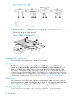
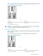
NOTE:
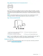
When adding a second device for configurations using a single SCSI bus.
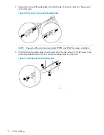
1.
Unplug the SCSI cable from device 1.
2.
Pass the end of the cable through internal chassis openings.
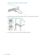
3.
Plug the end port into device 2.
4.
Then plug the middle port into device 1.
The SCSI terminator is at the end of the cable and should be behind device 2.
12
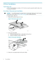
Drive Installation


