1-10
Chapter 1
Setting Up the Jukebox
Connecting a 4- or 6-Drive Jukebox
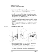
Refer to the following diagram in the next steps.
3. Select single-ended (“A”) or differential (“B”) interface using the SCSI
interface selection switch (see the arrow on the diagram ).
The diagram shows connecting a cable to the differential (“B”) interface.
4. Connect a cable between your host computer and either port of the jukebox
SCSI connectors of your selected interface type (the example diagram shows
using the “B2” port on the differential interface).
Route the cable through the slot at the bottom of the right side (“C”).
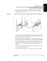
5. Plug a SCSI terminator into the unused SCSI port of interface type you chose
(the example diagram shows the terminator at “B1” because “B2” was used for
the cable ).
If you are using the differential interface, use a 68-pin high-density terminator.
If you are using the single-ended interface, use a 50-pin high-density active
terminator.
Figure 1-2
Connecting a 4- or 6-Drive Jukebox
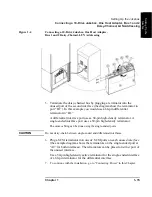
6. Plug a SCSI terminator into one of the SCSI ports on the unused interface.
Only one terminator is necessary on an unused interface.
The example diagram shows the terminator on the single-ended interface
connector “A2” but the terminator could have been placed on “A1”.
Use an active terminator if you are terminating a single-ended interface.
Summary of Contents for Surestore 660ex - Optical Jukebox
Page 10: ...x Figures ...
Page 12: ...xii Tables ...
Page 13: ...1 Setting Up the Jukebox ...
Page 35: ...Using Optical Disks 2 Using Optical Disks ...
Page 41: ...Operating the Jukebox 3 Operating the Jukebox ...
Page 81: ...Supplies and Customer Support A Supplies and Customer Support ...
Page 96: ...A 16 AppendixA Supplies and Customer Support Warranty ...
Page 97: ...Operation on a SCSI Bus B Operating This Jukebox on a SCSI Bus ...
Page 117: ...Safety and Regulatory Information C Safety and Regulatory Information ...
Page 122: ...C 6 Safety and Regulatory Information Declaration of Conformity Declaration of Conformity ...


