


1-2
Installation and Reference Guide
Introducing the Switch
1
The SFP Media Side
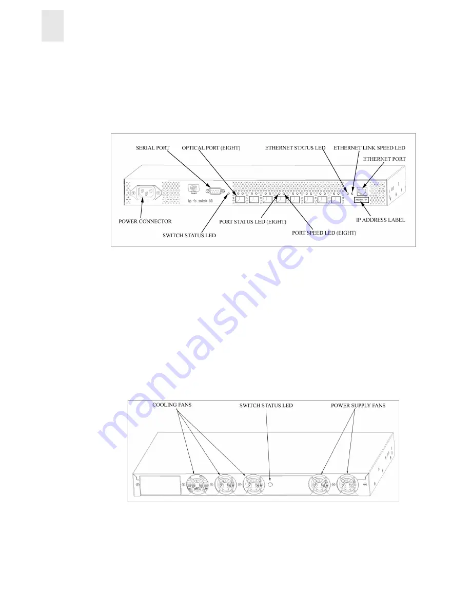
Figure 1-1
shows the SFP media side of the switch, which contains the power connector, IP label,
serial port, switch status LED, fiber optic ports and their corresponding LEDs, and the Ethernet port
and its corresponding LEDs.
Figure 1-1
The SFP Media Side of the FC Entry Switch 8B and FC Switch 8B
The switch ports are color-coded into two groups of four, to indicate which ports can be used in the
same ISL Trunking group.
Note:
ISL Trunking is a Fabric OS feature that enables distribution of traffic over the combined
bandwidth of up to four ISLs between two directly adjacent switches, while preserving
in-order delivery. For information about ISL Trunking, refer to the ISL Trunking User’s
Guide.
The Fan Side
Figure 1-2
shows the fan side of the switch, which contains the fans and the switch status LED.
Figure 1-2
The Fan Side of the FC Entry Switch 8B and FC Switch 8B


