Operation
2-2
HP Uninterruptible Power System T2200 XR Models User Guide
continued
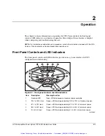
Item Description
Meaning/Function
6
Site Wiring Fault
Indicator (
)
Red—No ground connection exists between utility power and the UPS,
the line and neutral connections between utility power and the UPS
are reversed, or the UPS voltage configuration is incorrect.
7
Utility LED (
)
Flashing Red—Utility input voltage is outside the +20% to -30%
configured nominal range.
Green—Utility voltage is present and output is on, or utility voltage has
returned to the voltage range for which the UPS has been configured
(UPS is supplying utility power and the audible alarm should be reset).
Flashing Green—Utility voltage is present and the UPS is in Standby
mode. Output is off. Batteries charge if needed.
8 Bad
Battery/Low
Battery (
)
Red—Battery is bad or low.
9
On Battery (
)
Red—UPS is running on battery power.
10
General Alarm (
)
Red—UPS detects a general alarm. Perform a self-test.
11
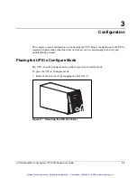
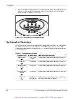
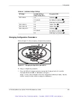
Configure Mode On
LED
Green—UPS is in Configure mode (seen when front bezel removed).
12 Configure
button
Places the UPS in Configure mode (seen when front bezel removed).
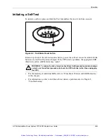
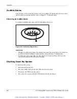
13 Test/Alarm
Reset
button
Resets alarms or initiates self-tests.
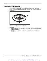
14
Standby button
Places the UPS in Standby mode (turns output load segments off).
15 On
button
Starts UPS powering the load.
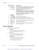
Modes of Operation
The UPS has three modes of operation:
•
Standby Mode
— No power is available at the UPS output receptacles.
— The UPS charges the batteries as necessary.
•
Operate Mode
— Power is available at the UPS output receptacles.
— The UPS charges the batteries as necessary.
•
Configure Mode
— Power is available at the UPS output receptacles.
— The UPS charges the batteries as necessary.
— The UPS configuration can be updated.
Artisan Technology Group - Quality Instrumentation ... Guaranteed | (888) 88-SOURCE | www.artisantg.com

