


Chapter 2
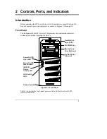
Controls, Ports, and Indicators
9
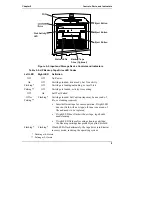
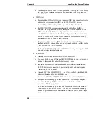
FDD
Backup Tape
Drive (Optional)
Eject Button
Eject Button
Eject Button
Status LEDs
Disk Activity
LED
Figure 2-2. Input and Storage Device Controls and Indicators
Table 2-2. HP Backup Tape Drive LED Codes
Left LED
Right LED
Definition
Off Off
No
Power
On
Off
Cartridge loaded, drive ready, but No activity
Flashing*
Off
Cartridge is loading/unloading, or in self-test
Pulsing**
Off
Cartridge is loaded, activity is occurring
Off
On
Self Test Failed
Off or
Pulsing**
Flashing*
Cartridge loaded, but Caution (tape may be near end of
life, or cleaning required)
•
Insert different tape for same operation. If right LED
does not flash with new tape, old tape is near end of
life and needs to be replaced.
•
If right LED does flash with new tape, tape heads
need cleaning.
•
If right LED flashes after using cleaning cartridge,
the cleaning cartridge has probably expired; discard.
Flashing*
Flashing*
If both LEDs flash alternately, the tape drive is in disaster
recovery mode, restoring the operating system.
* Flashing at 4-Hz rate
** Pulsing at 2-Hz rate


