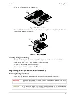
113
Chapter 7
Replacing Parts
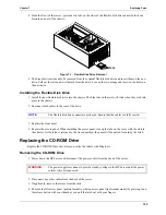
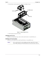
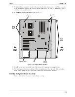
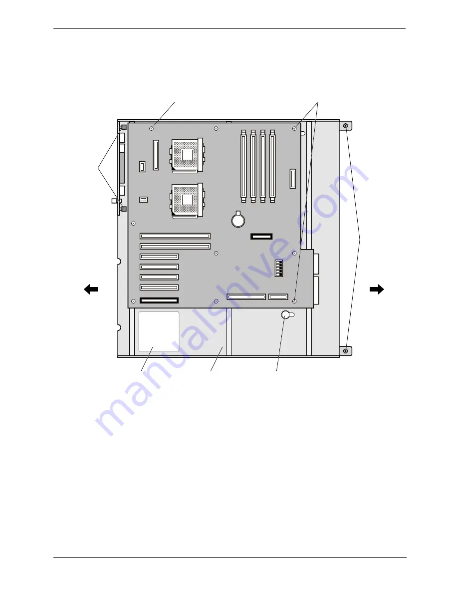
13. The System Board assembly is secured to the chassis by four blue thumbscrews. Two of these screws are
on the System Board assembly and closest to the front of the server. The other two thumbscrews are at the
rear of teh server inside the chassis.
14. Loosen the four captive thumbscrews. See .
Figure 7-12
Figure 7-12. Captive Screw Locations
15. Slide the system board towards the front of the system until it stops (approximately 1/2 inch).
16. Using the thumbscrews closest to the top of the server (pedistal model) or right side of the server (rack-
mount model), pull up and out to remove the System Board assembly out of the chassis.
Installing the System Board Assembly
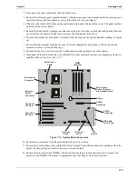
1. Install the new System Board on the System Board assembly.
W
ARN
IN
G
6
5
4
3
0
1
2
3
2
1
1
2
3
4
5
Warning Label
Tray
keySlot
(9 Places)
Captive
Thumb
Screws
Captive
Thumb
Screws
Standoff
(2 Places)
Screw
(6 Places)
Front of
System
Rear of
System

