background image

57

Chapter 3

Installing and Configuring

Guided Configuration 

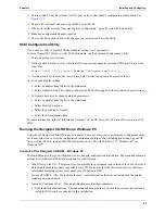
Guided configuration is the preferred method to configure your Server since it leads you through the 
configuration process in sequence and offers you default selections. Guided configuration includes the 
following steps: 

1.

Tested Configurations (Optional)

Presents information that should be viewed before configuring your system: 

Configuration Advisor (Recommended)

Lists caveats and exceptions based on your system, hardware installed, and NOS selection. 

Tested Products List (Optional)

Lists hardware and software products tested with HP Server systems.

2.

BIOS and Firmware Update

Updates your server's BIOS code and firmware with the versions on the CD. This step will be automatically 
skipped if there are no mismatches between the BIOS on the system and on the CD. 

3.

Disk Array Configuration

Allows you to run the disk array controllers (DAC) configuration utility. This step will be automatically 
skipped if there are no DAC's detected in the system. 

4.

Remote Management Device Configuration (Optional)

Allows you to run the configuration utility for the Remote Management Device (RMD) in the system. This 
step will be automatically skipped if is are no RMD detected in the system. 

5.

Diagtools Diskette Creation (Optional)

Takes you to the Diskette Library to create a Diagtools diskette. 

6.

Save Configuration to Diskette (Optional)

Allows you to save the current hardware configuration on to a diskette which can be used to replicate the 
configuration on another HP Server.

Select NOS: 

You will be asked to select the NOS and version you plan to install.

Select NOS Installation Mode: 

For certain versions of Novell NetWare/IntranetWare and Microsoft Windows NT/2000 Server, you will 
be asked:

Would you like to use HP's automated mode of NOS installation?

o Select Yes for automated NOS installation. 

Perform an automated NOS installation for first-time installation of Novell NetWare/IntranetWare 
or Microsoft Windows NT/2000 Server on a factory-configured Server. Automated NOS installation 
will guide you through the NOS installation, set up the hard disk drive, and configure your NOS with 
appropriate drivers for HP-bundled configurations. 

This installation also loads Instant Toptools onto Widows NT/2000 or NetWare systems. Instant 
Toptools is a stand-alone support tool accessed directly from the server. It gives you information to 
help you manage the server.

Automated NOS Installation: For certain versions of Novell NetWare/IntranetWare or Microsoft 
Windows NT/2000 Server, Configuration Assistant partitions and formats the hard disk drive, and 
Installation Assistant guides you through the NOS installation and configures the NOS with the 
appropriate drivers for the HP-bundled configuration.

o Select No for manual NOS installation. 

Perform a manual NOS installation if


you are installing a NOS other than certain versions of Novell 

NetWare/IntranetWare or Microsoft Windows NT Server, or if you have replaced any HP 
components.

Summary of Contents for Tc4100 - Server - 256 MB RAM

Page 1: ...HP Tower Server tc4100 Operations and Maintenance Guide Online Version 2 1 December 2002 ...

Page 2: ...vell and NetWare are registered trademarks of Novell Incorporated OS 2 is a registered trademark of the International Business Machines Corporation SCO and SCO UNIX are registered trademarks of The Santa Cruz Operation UNIX is a registered trademark in the United States and other countries licensed exclusively through X Open Company Limited pcANYWHERE32 is a trademark of Symantec Corporation Red H...

Page 3: ...igurations 15 Sleep States ACPI 15 2 External Connectors 16 Mini DIN PS 2 for Mouse and Keyboard 16 Serial Port 16 Parallel Port 17 USB 18 Standard Video 18 Standard SCSI 19 Standard LAN 20 3 Installing and Configuring 21 Opening and Closing the HP Server tc4100 21 Introduction 21 Removing the HP Server tc4100 s Covers 21 Removing Covers Pedestal 25 Removing the Pedestal 27 Mass Storage Devices 29...

Page 4: ...s PC 67 4 Error Messages 70 Power On Self Test POST Error Codes 70 Beep Codes 76 5 Diagnostics 78 Power On Self Test POST 78 No Error Messages Displayed 78 HP Server Diagtools 80 HP Toptools 82 6 Troubleshooting 83 Preventive Maintenance 83 Troubleshooting Tools 83 Troubleshooting Checklist 86 BIOS Reset Update Recovery 86 BIOS Reset 87 BIOS Update Recovery 87 Clearing the BIOS Configuration 87 Pa...

Page 5: ...Installing the CD ROM Drive 103 Replacing the Hot Swap Drive Cage Backplane 104 Removing the Hot Swap Drive Cage Backplane 104 Installing the Hot Swap Drive Cage Backplane 105 Replacing the Fan Assembly 105 Removing the Fan Assembly 106 Removing the Fan Tray 106 Replacing the Power Supply 108 Removing the Power Supply 108 Installing the Power Supply 110 Replacing the System Battery 110 Removing th...

Page 6: ...9 Specifications 122 System Details 122 Weight and Dimensions 122 Video Display Modes 122 Environment 124 Power Specification 124 Input Power Requirements 124 Power Ratings 125 Power Supply 125 Index 126 ...

Page 7: ... the controls ports and indicators on the front and rear of the HP Server tc4100 Figure 1 1 Figure 1 2 Figure 1 3 and Figure 1 4 below show the HP Server tc4100 as pedestal and rack models Figure 1 1 HP Server tc4100 Pedestal front view 1 Control and Indicators ...

Page 8: ...ators Figure 1 2 HP Server tc4100 Pedestal Bezel Figure 1 3 HP Server tc4100 Rack front view Hot Swap Hard Drives 8 bays CD ROM Drive Flexible Disk Drive Floppy Hard Drive Lock Non hot swap Drives optional Control Panel Indicators ...

Page 9: ...certain LEDs will function differently The table below describes the LED functionality with and without the HP Server Remote Management Card accessory i Hot Swap Hard Drives 8 bays CD ROM Drive Information Pullout Tab Control Panel Indicators Flexible Disk Drive Floppy Hard Drive Lock Non hot swap Drives optional Rack Tie Down Screw 2 places ...

Page 10: ...as three distinctive states Blank No Power Green Power on Green Flashing Sleep mode Reset Button Performs a system hard reset Keyboard Lock LED The Keyboard Lock LED has two distinctive states when the server is set to Network Server Mode through the BIOS setup program Blank Keyboard lock is not engaged Green Keyboard lock is engaged Locator Button LEDs There are two Locator Buttons one on the fro...

Page 11: ...responding LED indication System Status LED NOTE The installation of the HP Server Remote Management Card optional accessory changes this LED behavior If the HP Server Remote Management Card is installed this LED displays Green steady All components are OK Yellow blinking at a rate of 1 Hz An internal component may fail soon i e system fan speed below threshold predictive memory fail Check the int...

Page 12: ... turn OFF when the sensors return to normal Note that a system reset always returns sensors to normal If the error condition is still present when the system comes back up the sensor should go back to the error state within one minute Some LEDs are triggered by SEL events for example DIMM configuration error and will only be cleared by a system reset After resetting the LED should be cleared until...

Page 13: ...errors occur power down the server unplug the server from its power source re seat the DIMM and restart the HP Server tc4100 System Fan Incorrect fan speed predictive fan failure fan failure 1 Reseat system fan module 2 If the error is not resolved replace the system fans System Board System board voltage level error Reboot the HP Server tc4100 Memory Configuration Incorrect memory type Check that...

Page 14: ...tion ports the AC power inlets and the Server power supplies Figure 1 7 shows the HP Server tc4100s rear panel Figure 1 7 HP Server tc4100 Rear Panel Table 1 4 Hot Swap Hard Disk Drive LED Indications Status LED Activity Status LED Off Disk not present or not connected to the cage Off No disk activity Green solid Disk present Green flashing Accessing disk Amber flashing Disk failure predicted Gree...

Page 15: ... down on the release latch to free the power supply from the chassis Table 1 5 Power Supply LED Indicator Descriptions Green LED Power Supply and Server Status Steady Green This indicates that the output voltages are present It does not indicate the status of the HP Server tc4100 software Off This indicates the Server is powered off the AC line cord is unplugged or the power supply has failed whic...

Page 16: ...anel See Figure 1 5 Powering Down the HP Server tc4100 1 Log off all users and if necessary back up files Follow instructions in your network operating system NOS documentation to gracefully shut down all networking software and applications 2 Press the power switch on the HP Server tc4100 control panel when prompted by the operating system 3 Normally this completes the shutdown procedure Table 1 ...

Page 17: ...ith a slower wake up time sometimes referred to as hibernate by various operating systems In this sleep state the server appears to be off as described earlier but the fans and the front panel power LED are also turned off The unique feature of this sleep state and the reason for its slower wake up time is that information about the server s NOS state open applications screens and so on is saved t...

Page 18: ...ernal Connectors Table 2 1 Mini DN Signal Description Pin Number Signal Description 1 Data signal 2 Not used 3 Ground 4 Power 5 V dc 5 Clock signal 6 Not used Table 2 2 Serial Port Signal Description Pin Number Signal Description 1 Data carrier detect 2 Receive data 3 Transmit data 4 Data term ready 5 Signal ground 6 Data set ready 7 Request to send 1 2 5 6 4 3 5 4 3 2 1 9 8 7 6 ...

Page 19: ... Description Pin Number Signal Description 1 Strobe5 10 Acknowledgeb 2 Data bit 06 11 Busy 3 Data bit 1a 12 Paper end 4 Data bit 2a 13 Select 5 Data bit 3a 14 Auto line feedb 6 Data bit 4a 15 Error1 7 Data bit 5a 16 Initialize printerb 8 Data bit 6a 17 Select inb 9 Data bit 7a 18 25 Signal ground Table 2 2 Serial Port Signal Description Pin Number Signal Description 1 2 3 4 5 6 7 8 9 10 11 12 13 1...

Page 20: ...al Description 1 VBUS 2 D 3 D 4 GND NOTE Use of the USB port is supported for printers scanners and external modems Table 2 5 Standard VIdeo Pin Functions Pin Number Function Pin Number Function 1 Red 9 Key no pin 2 Green 10 Sync return ground 3 Blue 11 Monitor ID bit 0 4 Monitor ID bit 2 12 Monitor ID bit 1 5 Monitor self test ground 13 Horizontal sync 6 Red return ground 14 Vertical sync 7 Green...

Page 21: ...DB 0 23 S23 BSY 40 S40 DB 0 57 S57 BSY 7 S7 DB 1 24 S24 ACK 41 S41 DB 1 58 S58 ACK 8 S8 DB 2 25 S25 RST 42 S42 DB 2 59 S59 RST 9 S9 DB 3 26 S26 MSG 43 S43 DB 3 60 S60 MSG 10 S10 DB 4 27 S27 SEL 44 S44 DB 4 61 S61 SEL 11 S11 DB 5 28 S28 C D 45 S45 DB 5 62 S62 C D 12 S12 DB 6 29 S29 REQ 46 S46 DB 6 63 S63 REQ 13 S13 DB 7 30 S30 I O 47 S47 DB 7 64 S64 I O 14 S14 DB P 31 S31 DB 8 48 S48 DB P 65 S65 DB...

Page 22: ... Chapter 2 External Connectors Standard LAN Table 2 7 LAN Signal Description Pin Number Signal Description 1 Data signal 2 Not used 3 Ground 4 Power 5 V dc 5 Clock signal 6 8 Not used 8 1 GRN LED YEL LED ...

Page 23: ...ver If you are only installing or removing hot swap SCSI disk drives remove the bezel but do not extend the Server or remove the covers If you are only installing the redundant power supply you do not need to remove the bezel extend the Server or remove the covers 3 Installing and Configuring WARNING Before removing the covers shut down the operating system and disconnect the power cords and unplu...

Page 24: ...foot from under the front of the rack 6 Unscrew the slide securing screw 2 on each bracket securing the chassis to the column adapter on each side of the rack 7 Press in on each blue Slide Release button 2 with both hands to slide the HP Server tc4100 out of the rack 8 Pull the Server out of the rack until it snaps into the safety locks in each slide with a click NOTE The power supplies will conti...

Page 25: ...remove the top cover pull the latch up and lift the top cover away from the server See Figure 3 1 Figure 3 1 Removing HP Server tc4100 Covers 10 To remove the front bezel press down on the two self locking tabs as shown in Figure 2a 3a 1a 1 2 3 3 ...

Page 26: ...cover s tabs over the respective holes along the top edge on both sides of the chassis 16 Slide the cover toward the rear 17 Close the plastic latch 18 To replace the bottom cover position the cover s tabs under the respective holes along the bottom edge on both sides of the chassis 19 Slide the cover toward the rear 20 Close the plastic latch 21 Release the safety latches in the slide members on ...

Page 27: ...g off all users and if necessary back up files 2 Follow instructions in your network operating system NOS documentation to gracefully shut down all networking software and applications 3 Press the power switch on the HP Server tc4100 s control panel when prompted by the operating system Normally this completes the power down procedure 4 Disconnect the power cord s from its power source WARNING Do ...

Page 28: ...de cover by lifting the plastic latch The right cover only provides access to the Power Distribution Board and Floppy Disk Drive 7 Pull the cover forward and then slightly sideways to disengage it 8 Move it to the right and away from the chassis CAUTION To prevent damage to the covers support the cover as you remove it from the HP Server tc4100 The Server s covers can be easily damaged Note Remove...

Page 29: ...toward the rear 15 Close the plastic latch 16 To replace the bezel insert the tabs at the bottom of the bezel into the slots on the chassis 17 Swing the top of the bezel toward the chassis until it snaps into place Removing the Pedestal The pedestal version of the HP Server tc4100 mounts to an anti tip pedestal which can be easily removed if necessary 1 Perform Steps 1 4 in the previous section Re...

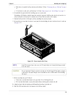
Page 30: ...ver over onto its top and pull up on the two tabs as shown in Figure 3 5 Figure 3 5 Removing the Pedestal 4 Slide the pedestal to the rear of the Server 5 To re install the pedestal repeat Steps 1 3 and slide the pedestal forward onto the Server 2 2 1 3 3 ...

Page 31: ...istant on the HP web site at http www hp com You may select Buy HP and choose the country and desired option that best suits your needs You may also download the Order Assistant utility Tools Required Torx T 15 driver non Hot Swap devices Drive Bay Shelves The non hot swap drives include the IDE CD ROM and the 3 5 inch flexible disk drives which are standard for all HP Server tc4100 models and shi...

Page 32: ...D 0 and proceeds up from there The HP Server tc4100 s boot order BIOS search order for a boot device should be considered when connecting cables from the on board SCSI channels By default the Server searches for boot devices in this order 1 IDE CD ROM drive 2 Flexible disk drive 3 SCSI A bus typically non Hot Swap internal SCSI devices 4 SCSI B bus typically Hot Swap Mass Storage Cage 5 PCI Slot 6...

Page 33: ...ts The HP Hot Swap drives come set for LVD SCSI operation and without device ID or termination Do not change these settings Use only 3 5 inch or 5 25 inch SCSI devices for the non Hot Swap shelves The available space in the non Hot Swap shelves supports two half height 1 6 inch devices You can order HP mounting kits for removable media devices or trays for 3 5 inch hard disk drives half height You...

Page 34: ... empty slots in the Hot Swap drive cage have filler panels inserted to ensure proper airflow If there are fewer drives than the Hot Swap drive cage supports a 1 inch filler panel must be inserted in each empty disk location The filler panels ensure the drive cage has the proper ventilation and airflow The filler panel will be removed before inserting a new drive Cabling Configurations There are va...

Page 35: ...system This cable can only connect to the floppy connector on the system board IDE Cable This cable always connects to the IDE devices CD ROM in the HP Server tc4100 This cable can only connect to the embedded IDE connector on the system board Round Twisted Pair SCSI Cable This cable always connects to the non hot swap drives and has a termination at the end This cable can be connected only to the...

Page 36: ... 5 4 3 0 1 2 3 2 1 1 2 3 4 5 Main Power Cable Two 64 bit PCI Slots Four 32 bit PCI Slots DIMM 4 places DIP Switch SCSI B Connector Misc Signal Cable To Power Distribution Board Battery SCSI A Connector IDE Cable To CD Drive To Floppy Drive To Control Panel Rear Locator Connector Intrusion Switch Connector ...

Page 37: ... the handle open See Figure 3 9 Figure 3 9 Opening the Drive Module CAUTION Protect the drive from static electricity by leaving it in its antistatic bag until you are ready to install it Before handling the drive touch any unpainted metal surface to discharge static electricity When you remove the drive from the antistatic bag handle it only by the frame Do not touch the electrical components If ...

Page 38: ... mass storage cage Removing Hot Swap Hard Drives 1 To unlock the drive push the locking latch in and then pull the ejector handle toward you 2 Gently pull the drive out about an inch to disengage the power connection 3 Wait about 30 seconds for the drive to stop spinning and the drive heads to park 4 Use your hand to support the bottom of the drive while you slowly pull the drive straight out Do n...

Page 39: ... panel 6 Configure the device according to the manufacturer s instructions Refer to SCSI addressing in Mass Storage Guidelines on page 31 7 If you are installing a boot device check the boot priority described earlier in this chapter 8 If the device does not already have a storage tray or mounting hardware install the appropriate mounting hardware on the device Refer to the directions included wit...

Page 40: ...Be sure to order the appropriate mounting kit HP product number Q1447A Table 3 2 SCSI Tape Drives Specification DRIVE Size Part No Supported Location Comments DLTVS 80i Half Height C7405A R1 or R2 P2 or P3 Use the plastic drive rails when installing DAT 40i Half Height C56864A R1 or R2 P2 or P3 Use the plastic drive rails when installing Ultrium 215i Half Height C7420A R1 or R2 P2 or P3 Use the me...

Page 41: ...have the correct DIMMs before installation refer to one of the following for a list of qualified DIMMs Technical Reference Label inside the HP Server tc4100 s top or side coverHP Order Assistant on the HP web site at http www hp com Information Assistant on the HP Server tc4100 Online Documentation CD ROM HP Customer Service CAUTION Do not use high voltage differential HVD SCSI devices on any of t...

Page 42: ...be loaded in any order Open slots between DIMMs are permitted When handling DIMMs observe antistatic precautions to avoid damage DIMM Installation Use this procedure to install each DIMM in a DIMM slot on the system board Figure 3 13 Individual SDRAM DIMM To install additional memory in the HP Server tc4100 1 To gain access to the HP Server tc4100 perform one of the procedures listed below If the ...

Page 43: ...The retaining clips should grasp the DIMM automatically if it is inserted properly If the clips do not close the DIMM is not inserted correctly Figure 3 15 Installing the DIMM 6 Re install the Air Scoop CAUTION Do not rock the DIMM into place but apply firm and even pressure If the retaining clips do not close remove the DIMM and repeat Steps 5 6 Memory Board DIMM DIMM Slot Notch 2 places Align Ke...

Page 44: ...efer to Opening and Closing the HP Server tc4100 on page 21 8 If the Server is in a rack installation return the chassis into the rack 9 Reconnect the power cord s 10 Power on the HP Server tc4100 according to the respective NOS power up instructions 11 Return the HP Server tc4100 to normal operation ...

Page 45: ... retaining clips to lift the DIMM s top edge away from the clips See Figure 3 14 5 Lift the DIMM completely away from the slot See Figure 3 14 6 Place the DIMM in its antistatic container 7 Re install the Air Scoop 8 If the Server is a rack installation return the chassis into the rack Refer to Opening and Closing the HP Server tc4100 on page 21 9 Re install the bezel onto the front of the HP Serv...

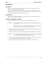
Page 46: ...ed of 133 MHz Both processor modules must be the same processor type and have the same product number which insures the same clock speed cache size and FSB speed The processor modules must operate at the designated speed stated by the product type on the processor Use only processor upgrade kits with the same HP product number This ensures the processor type clock speed and cache size match and th...

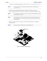
Page 47: ...procedure 4 Disconnect the power cords and any connected phone lines 5 To gain access to the system board follow the appropriate instructions for removing the cover If the Server is mounted on the pedestal perform Steps 1 8 from the Removing Covers Pedestal on page 25 CAUTION Use an antistatic wrist strap and a grounding mat Wear a wrist strap and use a static dissipating work surface connected to...

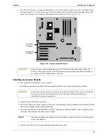
Page 48: ... lever and pulling the terminator upwards Figure 3 17 Remove Terminator Board NOTE It is not necessary to remove the system board from the Server to install the new processor module NOTE When installing a second processor the processor speed is set automatically No manual setting of switches is necessary NOTE The System board is shown removed from the HP Server tc4100 for simplicity in the followi...

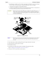
Page 49: ... includes the heat sink that sits on top of that processor Also the thermal grease is already applied to the bottom of the heat sink CAUTION Do not ingest or inhale the thermal grease heat sink compound Do not get it in your eyes Avoid prolonged skin contact which can cause irritation Wash with water any skin that contacted thermal grease If thermal grease gets in your eye flush the eye with water...

Page 50: ...he Air Scoop 16 Re install the cover and bezel onto the Server according to the appropriate procedure Refer to Opening and Closing the HP Server tc4100 on page 21 17 Return power to the Server and restore normal operation CAUTION Minimize any twisting or lateral sliding when installing the heat sink on the processor Ensure you have made good contact with the processor to avoid thermal overheating ...

Page 51: ...mote Management Card and the system board Boot Priority This section details the HP Server tc4100 s boot order by highest to lowest priority The Server s boot order BIOS search order for a boot drive should be considered when selecting a slot on the system board This is especially important if you are installing a SCSI disk controller board The disk controller s boot priority is set by the board s...

Page 52: ...h takes control of the IRQ sharing scheme You are not required to manually assign interrupts for the following NOSs Microsoft s NT 4 0 Novell s NetWare 5 SCO UnixWare 7 System Board PCI Slots All accessory boards plug into the six slots on system board at the rear of the Server s chassis Four PCI slots Slots 3 6 support full length 32 bit boards at a clock rate of 33 MHz These slots only support 5...

Page 53: ...hut down all networking software and applications 4 Press the power button on the HP Server tc4100 s control panel when prompted by the operating system Normally this completes the shutdown procedure 5 Gain access to the Server by performing the appropriate procedure CAUTION Some accessory board outputs may exceed U S National Electrical code NFPA 70 Class 2 or limited power source limits and must...

Page 54: ...ver s rear panel before installing the new board into the slot as shown in Figure 3 21 Figure 3 21 Removing the Slot Cover 9 Before installing the new PCI board Verify there is no handle attached to it especially if it is a full length board If it has a handle attached remove the handle before installing the board into the slot 10 Align the board with its slot along its full length and position it...

Page 55: ...e cable is properly attached Refer to the accessory board documentation for connection requirements 14 If accessory board installation is complete re assemble the Server 15 If all installation work is complete return power to the Server according to the respective NOS power up instructions 16 Use the respective NOS software to ensure the correct software drivers for the PCI board are loaded and ve...

Page 56: ...ere you can perform configuration tasks or create the diskettes required for installation including the Utilities The Information Assistant button directs you to the HP Server tc4100 Online Documentation CD ROM The menu buttons are Navigator Overview Describes the functions and modes available when using the HP Server tc4100 Navigator program whether at the server or client What s new on the CD Li...

Page 57: ...ge How to get additional support for your server via the web Product Registration Register your HP Server tc4100 and find out about the additional services HP offers to help keep your server up and running Before the HP Navigator main menu is displayed you may be prompted to set the language time and date You can also set the language displayed by the BIOS Refer to the following topics for more in...

Page 58: ...l your HP Server tc4100 Server Configuration Utility The Configure the Server utility guides you through the steps necessary to configure the HP Server tc4100 You can view configuration advisories at one step and change your hardware if necessary Three methods of configuration are available Guided Custom and Replication The HP Automated NOS Installation utility guides you through the NOS installat...

Page 59: ...u to save the current hardware configuration on to a diskette which can be used to replicate the configuration on another HP Server Select NOS You will be asked to select the NOS and version you plan to install Select NOS Installation Mode For certain versions of Novell NetWare IntranetWare and Microsoft Windows NT 2000 Server you will be asked Would you like to use HP s automated mode of NOS inst...

Page 60: ...NOS installation mode automated or manual and after you have viewed the Configuration Advisories the Custom Configuration screen displays the following menu Essential Steps Configure Disk Array This configures your HP disk array but requires you to fill out the Disk Array Configuration Worksheet before proceeding Click Help for more details Execute Card Utilities This executes the available config...

Page 61: ...Instructions that you printed out HP Management Solutions HP Management Solutions is a comprehensive suite of utilities applications and built in features to manage multiple HP Servers locally or from remote locations If you are unfamiliar with these products or concepts Go to the Management Web site on the HP Web Site at http www hp com to view information on HP Toptools and all other HP Server t...

Page 62: ...urity Text console redirection of the HP Server tc4100 console Full graphics console redirection of Microsoft Windows NT Servers across the network or over a modem connection using Symantec s pcANYWHERE software included with the system See the HP Server Remote Management Card User Guide for details PcANYWHERE pcANYWHERE is a remote control graphics redirection software from Symantec Corporation t...

Page 63: ...isable and then set the base I O address and IRQs of the serial ports Serial A and Serial B port and set the parallel port s parameters including its mode output only bi directional or DMA channel PCI Device Settings Use this menu to disable the Sharing Algorithm for each slot and manually set the IRQ for each PCI board installed into the six slots This menu also includes setting the IRQ Locking f...

Page 64: ...l arrow points precede some field names This means the field is actually a submenu To visit the submenu select it with the arrow keys and press the Enter key The submenu then appears in place of the current screen The Esc key is the exit key If you press the Esc key on one of the top level screens the Exit menu appears If you press Esc on a submenu the previous screen appears When you are making s...

Page 65: ... there is a submenu to select from 3 If necessary use the arrow key to move to the Power On Password menu selection and press Enter The Power On Password is highlighted by default when the Security menu is selected The first line in the menu is Administrator Password is Set or Not Set If no password has been set then Not Set will appear in the field If this is the case then you are not allowed to ...

Page 66: ...field Setting this feature enables the keyboard lock button on the front bezel of the HP Server tc4100 Once enabled pressing the keyboard lock button will lock the keyboard and mouse until the password is typed You must set the password before enabling this feature 15 To use the Hardware Security menu under Security use the help files provided with the selections 16 Select the Esc key to exit this...

Page 67: ...NOS on the first hard disk drive or DAC or SCSI board found in this list If no NOS is found the system tries the next logical hard drive in the list until a NOS is found 1 Bootable Cards 2 30 ID01 LUN0 HP 4 26GB A 3 30 ID02 LUN0 HP 4 26GB A 5 Use the plus or minus keys to move the desired hard drive or DAC or SCSI board to the top of the list The HD boot list has a maximum capacity of eight 8 logi...

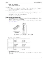
Page 68: ...ard Switches 1 To clear CMOS configurations using the System Board switch power down the HP Server tc4100 and open the side panel to gain access to the System Board 2 On the system board reset switch 4 on the configuration switch block from Off open to On closed See Figure 3 23 and Table 3 3 Figure 3 23 Configuration Switch Block Clearing CMOS 3 Power up the HP Server tc4100 4 When you see a messa...

Page 69: ...enu Select Device Selections Select the hard disk to format Select the Format menu option For more information refer to Information Assistant on the HP Server tc4100 Online Documentation CD ROM Running the Navigator CD ROM on a Windows PC Using the HP Navigator CD ROM in any Windows PC does not allow you to perform any configuration tasks but it does allow you to view the configuration instruction...

Page 70: ...not it provides you with the current Internet address for HP Support Product Registration This menu selection opens the Internet connection for registering your HP Server tc4100 and its installation if your PC has an Internet connection and a browser HP Server tc4100 Management Solutions This menu selection provides you with a comprehensive suite of utilities applications and built in features to ...

Page 71: ...Advisor under Guide to Configure Server The screens may display all or some of the following icons at the bottom of the screen Exit This icon allow you to exit the HP Navigator Program Toolbox This icon allows you to launch tools and utilities Overview This icon allow you to view configuration details Help This icon displays online help for the screen displayed or item selected Home This icon allo...

Page 72: ... Contact your service representative 0010 BIOS problem The PC configuration has been lost cleared corrupted or has not been initialized When the HP Server remains unplugged for a long period of time the battery will discharge and not provide enough current to keep the CMOS memory powered To correct this 1 Verify the battery is properly inserted 2 2 If necessary replace the battery as described in ...

Page 73: ...rify the keyboard connector is firmly connected 2 Reboot the server 3 If the problem persists your keyboard cable may be damaged or your keyboard may need to be replaced Contact your service rep resentative 0105 Mouse boot error The system board has detected a mouse error during POST To correct this 1 Clean the mouse and its moving ball as described in the User s Guide 2 If the problem persists yo...

Page 74: ...has detected the flexible disk drive A reported an error during its self test To correct this 1 Verify a diskette can be properly inserted and removed from the flexible disk drive 2 Verify the flexible drive type configured in the Setup utility matches the flexible disk drive installed in the HP Server 3 Verify all data cables and power cables are firmly connected 4 If the problem persists your fl...

Page 75: ... 0500 Hard Disk primary controller boot error POST has detected a general failure on the integrated primary hard disk controller To correct this 1 Restart your HP Server 2 If the error persists your system board may need to be replaced Contact your service representative 053X Hard Disk drive connection problem This does not apply to tc4100 Error code 0530 is the primary channel cable IDE1 and 0531...

Page 76: ...his 1 If some main DIMMs have just been removed or replaced by smaller ones press F4 to automatically validate the change 2 If no DIMM has been removed or changed ensure all DIMMs are properly inserted in the slots 3 If the problem persists one of DIMMs may need to be replaced Contact your service representative 0712 DIMM installation error POST has detected an incorrectly installed DIMM or the fa...

Page 77: ...ash utility on HP Navigator CD ROM 6 If the error persists the system board may need to be replaced Contact your service representative 0901 Integrated LAN enable error The system could not enable the integrated LAN To correct this 1 Reset the Integrated LAN by powering off the HP Server 2 Disconnecting the power cord for 20 seconds 3 Reconnect the power cord and power on the HP Server 4 If the er...

Page 78: ...ate your BIOS by running the flash utility from your Naviga tor CD ROM To do this insert the Navigator CD ROM in the CD ROM drive and power cycle your system 2 If updating your BIOS does not clear this error contact your ser vice representative 0B2x Defective Microcode Update The Microcode Update data block for the microprocessor is defective To correct this 1 Update your BIOS by running the flash...

Page 79: ...3 Test 8742 Keyboard Controller 1 3 4 1 RAM failure on address line xxxx 1 3 4 3 RAM failure on data bits xxxx of low byte of memory bus 2 1 2 3 Check ROM copyright notice 2 2 3 1 Test for unexpected interrupts 1 2 Search for ROMs One long two short beeps on checksum failure 1 One short beep before boot Table 4 2 Beep Codes Beeps POST Routine Description ...

Page 80: ...n white background Press the Return key to see a definition of the message and what action to take to remedy the problem Power on self test POST errors These display in normal video white text on black background and may be a text message or an alpha numeric code If an error with a text message occurs during the POST details of the error are displayed Follow the instructions on the screen If an al...

Page 81: ...you have changed any switches on the system board verify that each one is properly set 5 Close the side panel and connect all cables 6 Turn on the monitor and server 7 If the server still does not work Repeat steps 1 2 and 3 of this section Remove all accessories except the primary boot hard disk drive Close the side panel and connect all cables Turn on the monitor and the server If the server now...

Page 82: ...essage Corrective Action Operating system not found Verify that the desired boot drive has power and its SCSI cable is connected Verify that the SCSI cable is securely plugged into the SCSI connector on the system board Verify that the boot device is enabled in the Setup Utility under the Security menu Verify that the boot device has an operating system installed If the problem persists contact yo...

Page 83: ... of advanced tests Add the record of results of advanced tests to the record of basic tests View a list to locate the meaning of a specific error code View one or more steps to help confirm and isolate error conditions Browse the support ticket which contains the detailed inventories and test results Add comments to the support ticket About Error Messages A hexadecimal number designates each error...

Page 84: ... Instant Toptools provides the same information as HP Toptools but is run directly at the server HP Instant Toptools is automatically installed on your server when using the HP Server Navigator CD to install your Network Operating System HP Toptools Auto Alert may be installed either from the HP Toptools CD ROM or the HP Server Navigator CD ROM See the HP Server Management Reference Guide for deta...

Page 85: ... tools Diskette Library A collection of diskette images representing drivers utilities and BIOS updates which enables you to conveniently generate any flexible disk available on the HP Server Navigator CD ROM 6 Troubleshooting Table 6 1 Preventative Maintenance Procedures Component Time Frame Maintenance Procedure Keyboard Regularly Dust with a damp lint free cloth Lock the keyboard if there is th...

Page 86: ...ing and information Technical information Data sheets application notes configuration guides installation tips product papers reference material and more Compatibility Information HP Accessories OS NOS HP and third party products Manuals Easy installation and configuration manuals for the HP Server Parts and Service Information on replacement parts exploded views and configuration Tape backup supp...

Page 87: ...n for any beep codes as the HP Server goes through POST then look up the error message in Chapter 5 of this Service manual If the HP Server passes POST the HP DiagTools Utility can be used to further test the hardware Use HP DiagTools Utility whenever possible to detect hardware problems Insert the HP Startup CD ROM into the CD ROM drive and reboot the HP Server Run HP DiagTools from the Startup C...

Page 88: ... Check all cable and power connections including those in the rack If the HP Server is not powering on unplug the AC power cords and wait 20 seconds then plug the AC power cords in again and restart the HP Server Check for normal operation 9 Verify that all cables and boards are securely plugged into their appropriate connectors and slots If the problem still persists 10 Simplify the HP Server s c...

Page 89: ...start and you will be prompted to update the system BIOS 5 After the BIOS update is complete remove the BIOS update diskette and then reboot the HP Server 6 Press F2 to enter the BIOS Setup Utility and make the necessary changes needed in the BIOS Setup Utility press F10 to save the changes and exit the utility 7 Label date and save this flexible diskette for use as a BIOS Recovery diskette Cleari...

Page 90: ...e changes to save the configuration and exit the Setup Utility Password Problems The only way to resolve the issue of a forgotten Supervisor password is to clear the password by using the appropriate dipswitch on the system board Refer to the appropriate HP Server Operation and Maintenance Guide for the location of the password dipswitch Supervisor Password 1 Power off the HP Server Remove the cov...

Page 91: ...pears reboot the HP Server and when prompted enter the system BIOS Setup Utility and check that the device boot order is correct 4 If a disk array controller is being used and the NOS is installed on a hardware array container verify that the array container is in an optimal state by accessing and checking the disk array controller s setup utility during startup 5 Boot to a DOS boot disk and check...

Page 92: ...dible and the above steps are verified a Disconnect the power cord s for five minutes in order to reset the power supply s circuitry b With the power cord s disconnected remove the HP Server cover c Remove all the accessory boards including any hard disk drive controller board or video board Disconnect all mass storage power cords and cables d Plug the power cord s back in and turn on the HP Serve...

Page 93: ...ll restore video If there is still no video 8 Power off the HP Server and unplug form the power source 9 Remove all PCI controller cards 10 Disconnect power and SCSI connections from tape drives and hard drives 11 Disconnect IDE and flexible disk drive cables 12 Take the HP Server down to base memory 1 DIMM and reseat that DIMM NOTE The HP Server tc4100 supports the ACPI Advanced Configuration and...

Page 94: ...tor CD and set the date and time from the appropriate menu See if this resolves the issue 3 If this does not resolve the issue replace the CMOS battery The battery is attached to the system board Turn off AC power to the HP Server Unplug the HP Server s power cords from the power source Remove the covers and locate the CMOS battery on the system board and replace the battery Power on the HP Server...

Page 95: ... Support Center for further assistance Keyboard Problems If the keyboard does not work or a character is not displayed when a key is pressed 1 Ensure that the keyboard is not locked if the HP Server has this feature 2 Ensure that the keyboard cable connections at the rear of the HP Server and at the back of the keyboard are secure 3 If the KVM switchbox is used with this HP Server remove the keybo...

Page 96: ...p Utility F2 on POST when prompted and verify the mass storage configuration is correct 4 Ensure the disk is not write protected 5 Ensure that the disk drive is trying to be accessed Look for an activity light on the drive 6 Try another flexible disk 7 Boot to the HP Navigator CD and try creating a disk form the Diskette Library This will eliminate the NOS causing the problem since the Navigator i...

Page 97: ...t a CD ROM disk is in the CD ROM drive c Verify that all internal drive cables are securely attached and functional 3 Verify that the Local Bus IDE Adapter item is correctly configured in the Setup program 4 Power on the HP Server and press F2 to enter the BIOS Setup Utility when this option displays 5 Check that Both is selected in the Local Bus IDE Adapter field If the problem persists contact t...

Page 98: ...o this b Repeat step 3 5 If you installed more than one SCSI controller try disabling the BIOS on all other SCSI controller except for the SCSI boot controller This lets the SCSI BIOS for the boot controller load and prevents conflicts with other SCSI controllers If necessary remove all the other SCSI controller boards except the SCSI boot controller until the issue is resolved Contact the HP Cust...

Page 99: ...esource used by another SCSI controller board c Try the accessory board in another slot 4 Check for any recent changes or upgrades to the software For example has anyone moved removed or changed the configuration files or drivers Refer to the software documentation for more information 5 If you suspect hardware failure and there are no system error messages check each component associated with the...

Page 100: ...version The most recent version is listed on HP s website 10 Verify the SCSI bus is terminated at both ends By default HP Server SCSI controllers in external enclosures are terminated When a device is connected to a connector on the SCSI bus bus termination for that connector is disabled Verify the last device on the bus is terminated Contact the HP Customer Support Center for further troubleshoot...

Page 101: ...r further troubleshooting assistance if needed Network Interface Card Embedded or PCI Problems If the adapter cannot connect to the network If the HP Server cannot connect to the network and all the LEDs are lit on the NIC 1 Verify that there are no resource conflicts between the NIC and any other accessory Do this from the system BIOS Setup Utility F2 on POST when prompted 2 Reboot the HP Server ...

Page 102: ...the following 2 Power off the HP Server and unplug the power cord s from the power source Remove the left side cover 3 Locate the NIC and reseat it in its slot 4 Replace the covers plug in the power cord s to a power source and power on the HP Server 5 If the problem persists perform previous step 2 and 3 but move the NIC to another slot 6 Replace the covers plug in the power cord s to a power sou...

Page 103: ...bles from the back of the server 3 If applicable remove the server from the rack 4 Remove the right access panel pedistal model or the bottom access panel rack mount model by pressing in on the release button with your thumb as you pull the latch out with your fingers 5 When the latch is fully lifted the access panel slides back towards the rear of the server The panel can then be lifted off the s...

Page 104: ...l When installing the access panel line up the tabs on the cover with the slots in the chassis As the latch is returned to the closed position the panel will be pulled forward by the latch Replacing the CD ROM Drive Replace the CD ROM Drive only after you verify the failure with Diagtools Removing the CD ROM Drive 1 Power down the HP Server and disconnect the power cord s from the back of the serv...

Page 105: ... CD ROM drive and slide the CD ROM drive forward out of the chassis Figure 7 2 Removing the CD ROM Drive 11 The blue plastic rails need to be removed from the original CD ROM drive and insert them on the new drive Pull out the rail and it will detach from the drive Line up the two prongs and insert in the holes on the new drive Installing the CD ROM Drive 1 Install the new CD ROM drive into the ch...

Page 106: ...fted off the server chassis 7 Remove the front bezel by pushing in on the tabs at the top of the bezel on both sides and pulling the bezel out away from the chassis Do the same to release the bottom part of the bezel 8 Remove blue plastic Air Scoop that is attached to the fan cage and the System Board by pulling it straight out 9 Remove the fan assembly from the fan cage locate the thumbscrew and ...

Page 107: ...crews 2 To reinstall it in the chassis align the mount plate into the metal rail and slide the mount plate into position making sure that all cables are out of the way Secure the mount plate to the chassis with the blue thumbscrew 3 Reverse the steps listed above to reassemble the server Replacing the Fan Assembly Replace the Fan Assembly when the system indicates slow or failing fans The fans are...

Page 108: ...hed to the fan cage and the System Board by pulling it straight out 7 Remove the fan assembly from the fan cage locate the thumbscrew and loosen it Pull out on the fan assembly to remove it from the fan cage Figure 7 4 Fan Assembly Removal Removing the Fan Tray 1 Remove the air duct by un snapping the latch on the top of the air duct and lifting the air duct up 2 Remove the air baffle by un snappi...

Page 109: ... the new fan tray and air scoop then reverse the steps listed above to reassemble the server Installing the Fan Assembly Install the new fan assembly then reverse the steps listed above to reassemble the server NOTE Wear a wrist strap and use a static dissipating work surface connected to the chassis when handling components Ensure that the metal of the wrist strap contacts your skin Air Scoop Fan...

Page 110: ... that the status LEDs for both supplies glows green Removing the Power Supply 1 Locate the desired power supply for removal Refer to Figure 7 6 for location of power supply status LEDs Figure 7 6 Power Supply Rear Panel WARNING If a power supply bay is not in use be sure to keep the cover on it If you do not system ventilation and EMI electro magnetic interference suppression may be affected Alway...

Page 111: ... AC power cord from the inlet on the supply 3 Loosen the two captive screws 4 Grasp the handle and use your thumb to depress the release latch 5 Pull the power supply out of the chassis Figure 7 8 Removing Power Supply Power Supply 1 Power Supply 2 or Filler panel Filler panel ...

Page 112: ...ower down the HP Server Refer to Powering Down the HP Server tc4100 on page 14 2 Disconnect the power cord s 3 If rack mounted extend the HP Server out of the rack 4 Remove the left cover pedestal or top cover rack mounted Refer to Opening and Closing the HP Server tc4100 on page 21 5 Remove the air scoop Refer to Removing the Fan Assembly on page 106 WARNING There is a danger of explosion if the ...

Page 113: ... clip is in place and holds the battery firmly 3 To complete battery replacement reverse steps 1 7 4 If necessary reset the date and time on the HP Server Replacing the System Board Assembly Removing the System Board 1 Power down the HP Server and disconnect the power cord s from the back of the server WARNING The power supplies continue to provide standby voltage to the HP Server until the power ...

Page 114: ...ove it from the fan cage 8 Remove the fan cage by unscrewing the two thumbscrews then pulling it out of the chassis 9 Disconnect all the cables from the System Board The cable configuration may vary depending on what is installed in the system See Figure 7 11 Figure 7 11 System Board Connectors 10 Remove the power cable from the plastic holder on top of the chassis 11 Remove the Control Panel cabl...

Page 115: ...ons 15 Slide the system board towards the front of the system until it stops approximately 1 2 inch 16 Using the thumbscrews closest to the top of the server pedistal model or right side of the server rack mount model pull up and out to remove the System Board assembly out of the chassis Installing the System Board Assembly 1 Install the new System Board on the System Board assembly WARNING 6 5 4 ...

Page 116: ...ssis 6 Remove blue plastic Air Scoop that is attached to the fan cage and the System Board by pulling it straight out 7 Remove the fan assembly from the fan cage locate the thumbscrew and loosen it Pull out on the fan assembly to remove it from the fan cage 8 Remove the fan cage by unscrewing the two thumbscrews then pulling it out of the chassis 9 With the fan cage removed the backplane SCSI conn...

Page 117: ... Installing the Power Distribution Board 1 Install the new Power Distribution Board 2 Reverse all the previous steps to reassemble the server 3 Replace the access panel When installing the access panel line up the tabs on the cover with the slots in the chassis As the latch is returned to the closed position the panel will be pulled forward by the latch Replacing the Diagnostic Board You will only...

Page 118: ...board 6 Push the diagnostic board cover to the right lift the board from the chassis 7 Separate the diagnostic board from the cover The cover will be used with the replacement diagnostic board Installing the Diagnostic Board 1 Install the replacement diagnostic board in the cover saved earlier WARNING The power supplies continue to provide standby voltage to the HP Server until the power cord s is...

Page 119: ...op cover rack mounted from the HP Server Refer to Opening and Closing the HP Server tc4100 on page 21 Figure 7 15 Control Panel 5 Remove three screws securing the control panel to the chassis 6 Remove the signal connectors from the Control Panel Installing the Control Panel Install the replacement control panel by reversing the procedure Removing the Control Panel on page 117 WARNING The power sup...

Page 120: ... Server tc4100 replaceable parts The complete list and description of these parts is in Table 8 1 on page 120 Covers Fans Chassis Parts and Mass Storage Figure 8 1 Covers Fans Chassis Parts and Mass Storage 8 Parts Information 1 2 3 4 6 7 8 9 10 11 3 5 18 12 13 14 16 17 15 2 ...

Page 121: ...119 Chapter 8 Parts Information Power Supplies and Chassis Parts Figure 8 2 Power Supplies and Chassis Parts System Board Parts Figure 8 3 System Board Parts 19 20 21 22 23 24 10 25 27 28 26 ...

Page 122: ...bel P3537 63019 6 System Fan Assembly P3537 67005 7 Air Scoop P3537 67004 8 Fan Tray Not Replaceable 9 System Board Assembly P3537 63011 P3537 69011 10 CD ROM Half Height IDE D4384 63003 HH CD ROM Rail Wire Assembly P2521 63041 11 FDD 5065 7466 FDD Rail Wire Assembly Left P2521 67005 FDD Rail Wire Assembly Right P2521 67006 12 Hot Swap Hard Drive 13 Hot Swap HDD Filler Panel A6198 67001 14 Rack Be...

Page 123: ...h Right P2521 63046 SCSI Jumper Cable P2521 63030 Locator Switch Cable Assembly P3537 63014 Hot Swap HDD Cage SCSI Cable P3537 63005 Non Hot Swap HDD SCSI Cable P2521 63019 Duplex SCSI Cable Optional P2521 63020 UDMA IDE CD ROM Cable P3537 63003 FDD Cable P3537 63004 Control Panel Cable P2553 63031 Diagnostic Board Cable P2521 63024 Fan Extension Cable P2521 63025 Power Supply to Power Dist Cable ...

Page 124: ...in Width 480 mm 18 9 in Depth 721 mm 28 4 in Weight 36 kg 80 lb This weight excludes monitor and keyboard Table 9 2 Weight and Dimensions Pedestal Version Height 472 mm 18 6 in Width 345 mm 13 6 in Depth 721 mm 28 4 in Weight 36 kg 80 lb This weight excludes monitor and keyboard Table 9 3 Video Specifications Sorted by Color Depth Resolution Color Depth Refresh Frequency HZ 640 X 480 256 60 72 75 ...

Page 125: ...5 85 90 100 120 640 X 480 16 7M 60 72 75 85 90 100 120 640 X 480 True Color 32 bit 60 72 75 85 90 100 120 800 X 600 256 60 70 72 75 85 90 100 800 X 600 64K 60 70 72 75 85 90 100 800 X 600 16 7M 60 70 72 75 85 90 100 800 X 600 True Color 32 bit 60 70 72 75 85 90 100 1024 X 768 256 60 70 72 75 85 90 100 1024 X 768 64K 60 70 72 75 85 90 100 1024 X 768 16 7M 60 70 72 75 85 90 100 1024 X 768 True Color...

Page 126: ...o 12 180 m 40 000 ft Acoustic Emissions Sound Level LpA 43 dB A bystander position Table 9 6 Input Power Requirements Input Voltage and Frequency 100 240 10 50 60 Hz Maximum Inrush Current 8 AMPs peak for 1 power supply 120 VAC or 16 AMPs peak for 2 power supplies 16 AMPs peak for 1 power supply 240 VAC or 32 AMPs peak for 2 power supplies Delayed Action Circuit Breaker Recommended North America a...

Page 127: ...wer Ratings AC Input Voltages Maximum Input Power VA Maximum Input Power W Maximum Operating Current RMS AMPS 100 VAC 650 643 6 5 120 VAC 640 628 5 3 208 VAC 625 605 3 0 230 240 VAC 630 603 2 6 Table 9 8 Power Supply Recommended Single Unit Input Type Wide Range PFC Input Voltage and Frequency 100 127VAC 10 50 60Hz 200 240VAC 10 50 60Hz Power Availability 425 W continuous Maximum Cold Inrush Curre...

Page 128: ...t 20 Mini DIN for mouse and keyboard 16 parallel port 17 66 88 SCSI 19 serial port 16 standard video 18 USB 18 external SCSI devices connecting 39 F fan assembly replacing 105 Figure 3 1 23 Figure 3 2 24 flexible disk drive replacing 101 front panel controls 5 front panel indicators 5 9 FSB front side bus 44 H hot swap disk drive indicators 12 hot swap drive cage backplane replacing 104 hot swap h...

Page 129: ... supply indicator 13 power supply LED 9 powering down server 14 powering up server 14 preventive maintenance 83 processors FSB 44 installing 44 supported processors 44 R rack removing 22 safety locks 22 readme file 56 68 rear panel indicators 12 rear panel ports 12 Remote Managemet Card slot location 49 removing DIMM 43 hot swap hard drive 36 removing covers 21 25 replicate configuration 58 reset ...

Page 130: ...optools for servers 59 troubleshooting CD ROM drive problems 94 common problems 85 configuration 92 memory problems 98 NIC problems 99 password problems 88 POST error messages 79 printer datacomm problems 92 troubleshooting checklist 86 Troubleshooting tools 83 U USB external connector 18 user password setting 64 utilities changing system date 62 ...

Reviews: