


4 Troubleshooting Your Personal Workstation and Using the Setup Program
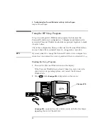
Using the HP Setup Program
96
English
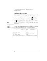
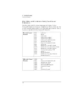
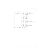
Viewing the Options
menu
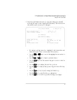
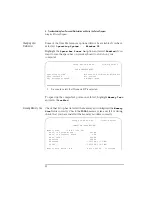
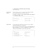
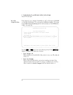
When you run the SCSISelect utility, the Options menu is displayed.
Use the
and
keys and the
key to make selections in
the SCSISelect utility. Press
at any time to return to the previous
menu.
SCSISelect(TM) Utility v1.xxx
Would you like to configure the interface, or run the
SCSI disk utilities? Select the option and press <Enter>.
Press <F5> to switch between color and monochrome modes.
Options
Configure/View Interface Settings
SCSI Disk Utilities
Arrow keys to move cursor, <Enter> to select option, <Esc> to exit
Summary of Contents for VECTRA XW
Page 1: ...HP Vectra XW User s Guide ...
Page 3: ...User s Guide ...
Page 12: ...xii English ...
Page 129: ...6 Hewlett Packard Support and Information Services ...
Page 152: ......
Page 153: ...Regulatory Information and Warranty ...
Page 161: ......
Page 162: ...Part Number Printed in 50 D4514 90001 USA 8 96 ...