

D–18
Service and Technical Reference Guide, xw3100
Troubleshooting Without Diagnostics
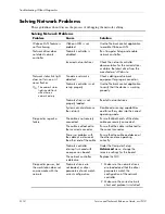
Solving Network Problems
These guidelines do not discuss the process of debugging the network cabling.
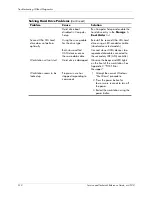
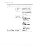
Solving Network Problems
Problem
Cause
Solution
Wake-on-LAN feature is
not functioning.
Wake-on-LAN is not
enabled.
Use the Network control application
to enable Wake-on-LAN.
Network driver does
not detect network
controller.
Network controller is
disabled.
Run Computer Setup and enable
network controller.
Incorrect network driver.
Check the network controller
documentation for the correct driver
or obtain the latest driver from the
manufacturer’s Web site.
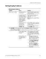
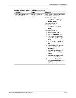
Network status link light
does not turn on or it
never flashes.
✎
The network status
light should flash
when there is
network activity.
No active network is
detected.
Check cabling and network
equipment for proper connection.
Network controller is not
set up properly.
Use the Network control application
to verify that the device is working
properly.
Network driver is not
properly loaded.
Reinstall network drivers.
System cannot autosense
the network.
Disable auto-sensing capabilities
and force the system into the correct
operating mode.
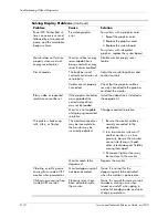
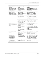
Diagnostics reports a
failure.
The cable is not securely
connected.
Ensure that both ends of the data
cable are securely connected.
The cable is attached to
the incorrect connector.
Ensure that the cable is attached to
the correct connector.
There is a problem with
the cable or a device at
the other end of the cable.
Ensure that the cable and device at
the other end are operating
correctly.
Network controller
interrupt is shared with
an expansion board.
Under the Computer Setup
Advanced
menu, change the
resource settings for the board.
The network controller
is defective.
Replace the NIC.
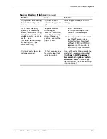
Diagnostics passes, but
the workstation does not
communicate with the
network.
Network drivers are
not loaded, or driver
parameters do not match
current configuration.
1. Make sure the network drivers
are loaded and that the driver
parameters match the
configuration of the network
controller.
2. Make sure the correct network
client and protocol is installed.
Summary of Contents for Workstation xw3100
Page 6: ...vi 338611 001 Service and Technical Reference Guide xw3100 Contents ...
Page 10: ...1 4 338611 001 Service and Technical Reference Guide xw3100 Installing the Operating System ...
Page 106: ...C 8 Service and Technical Reference Guide xw3100 POST Error Messages ...
Page 132: ...D 26 Service and Technical Reference Guide xw3100 Troubleshooting Without Diagnostics ...
Page 144: ...G 6 Service and Technical Reference Guide xw3100 Ultra ATA Drive Guidelines and Features ...


