background image


2


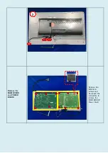
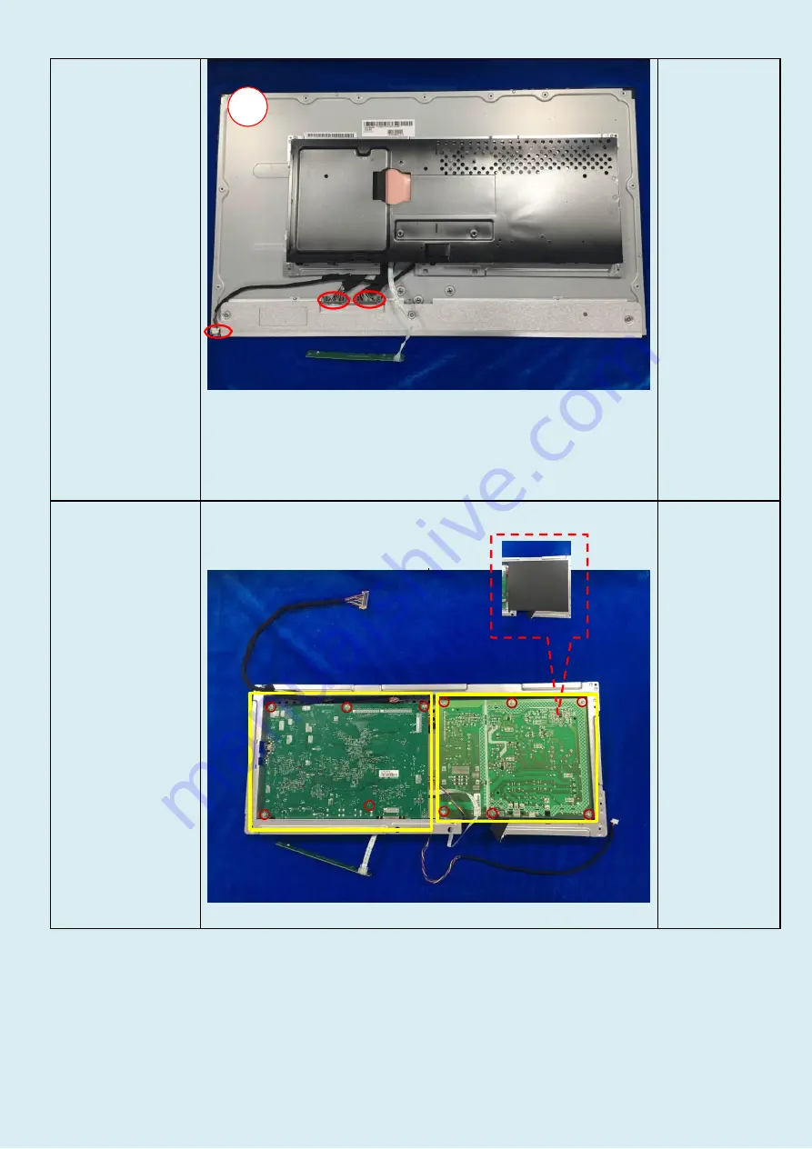
Remove  the 
MAIN  BOARD


and POWER


BOARD


Remove  the 
MAYLR  & 
screws  and 
disconnect  the 
connectors  to 
remove  the 
MAIN  BOARD 
Power  board 

Summary of Contents for Z27n G2

Page 1: ...ve treatment in the right column as applicable Item Description Notes Quantity of items included in product Printed Circuit Boards PCB or Printed Circuit Assemblies PCA With a surface greater than 10 sq cm 3 Batteries All types including standard alkaline and lithium coin or button style batteries 0 Mercury containingcomponents For example mercury in lamps display backlights scanner lamps switches...

Page 2: ... Disassembly Process 3 1 List the basic steps that should typically be followed to remove components and materials requiring selective treatment 1 Dismantle the hinge ass y via quick release bottom 2 Remove the screw and dismantle the back cover of monitor with tool 3 Remove middle frame with tool 4 Tear out all tapes 5 Dismantle the screws from Mainframe 6 Pull out the PIN of cables separate the ...

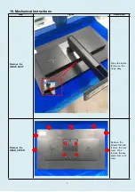
Page 3: ... Instructions Step Figure Description Remove the HINGE ASS Y Press the button to remove the hinge assy Remove the REAR_COVER Remove the screws first and remove the rear cover then remove the key board from rear cover ...

Page 4: ...2 Separate the MAINFRAME and PANEL 1 1 1 Remove the screws 2 disconnect the connectors tear out all tapes anddisconnect the connectors toseparate the MAINFRAME and PANEL ...

Page 5: ...3 2 Remove the MAIN BOARD and POWER BOARD Remove the MAYLR screws and disconnect the connectors to remove the MAIN BOARD Power board ...

Page 6: ...4 ...

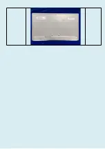
Page 7: ...5 Remove the Bezel panel Separate the Bezel panel ...

Page 8: ...6 ...

Reviews: