M 830 LL - M 830 M
User Manual
157
- steer the vehicle,
- aid handling and braking,
- aid vehicle suspension.
I - Tyre
The actual tyre is the main part of the overall
tyre in contact with the road and is therefore designed
to withstand internal air pressure and all other stress
arising from use.
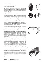
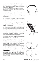
A tyre section shows the various parts it consists of:
1 - The tread
. This is the part in contact with the ground
when the tyre rolls. It comprises a rubber compound
and a “pattern” that is suitable for ensuring good
resistance to abrasion and good grip in dry and wet
conditions, as well as quiet operating conditions.
2 - Edge or bracing
. This is a metal fabric or textile insert,
in the area of the outer bead part. It protects the cas-
ing plys from rubbing against the rim.
3 - Casing
. This is the resistant structure and comprises
one or more layers of rubber plys. The way the plys
comprising the casing are arranged give the structure
its name. The following structures are possible:
Conventional:
the plys are inclined and arranged so
that the strands comprising a ply overlap with those
of the adjacent ply. The tread, which is the part of the
tyre in contact with the ground, is part of the sidewalls
and so during rolling, sidewall flexure is transmitted
to the tread.
Radial:
the casing consists of one or more plys with
the cords in a radial direction.
A radial casing in itself is quite unstable. To make
it stable and prevent bad tread movement in the
area of contact with the ground, the casing and the
undertread are reinforced with an annular structure,
usually called belt. The tread and sidewall work with
different, independent rigidities, so during rolling,
sidewall flexure is not transmitted to the tread.
4 - Side ring.
This is a metal ring comprising several steel
strands. The casing plys are secured to the side ring.
5 - Belt
. This is a non-flexible circumferential structure
comprising cross-plys at very low angles, positioned
below the tread, to stabilise the casing in the foot-
print area.
I
III
II
IV
1
12
13
8
3
5
9
Summary of Contents for M 830 LL
Page 37: ...M 830 LL M 830 M User Manual 123 A B C 1 2 D 17...
Page 38: ...124 M 830 LL M 830 M User Manual A B C D 1 2 2 18...
Page 49: ...M 830 LL M 830 M User Manual 135 1 2 3 4 30...
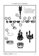
Page 76: ...162 M 830 LL M 830 M User Manual M13 M14 M11 M7 M2 M9 A M16 STANDARD RIM...
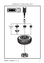
Page 77: ...M 830 LL M 830 M User Manual 163 M6 M5 M11 M7 M9 B M16 DROPPED CENTRE HOLE RIM...
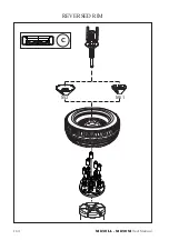
Page 78: ...164 M 830 LL M 830 M User Manual C M11 M2 REVERSED RIM...
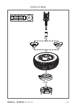
Page 79: ...M 830 LL M 830 M User Manual 165 D M10 M2 M15 M9 PICK UP RIM...
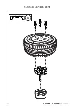
Page 80: ...166 M 830 LL M 830 M User Manual E CLOSED CENTRE RIM...
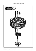
Page 81: ...M 830 LL M 830 M User Manual 167 F OPEN CENTRE RIM...
Page 84: ...170 M 830 LL M 830 M User Manual...
Page 85: ...M 830 LL M 830 M User Manual 171 49...

