background image

94  

M 830 LL - M 830 M 

User Manual

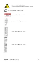
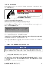
   WARNING: Indicates a potentially hazardous situation which, if not avoided, could 

result in death or serious injury.
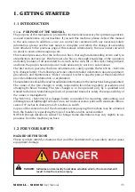
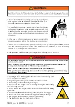
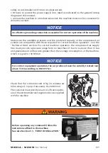
WARNING

   CAUTION: Indicates a potentially hazardous situation which, if not avoided, may 

result in minor or moderate injury.
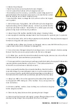
CAUTION

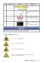
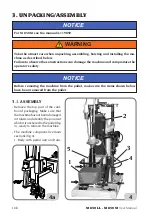
   NOTICE:    Used without the safety alert symbol, indicates a potentially hazardous 

situation, which, if not avoided, may result in property damage.

NOTICE

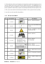
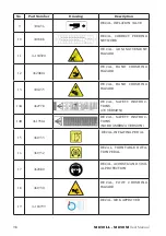
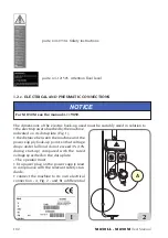
1.2.a.  GENERAL WARNING AND INSTRUCTIONS

Avoid Personal Injury.  Carefully read, understand and follow the warnings and instructions given in this manual.  
This manual is an essential part of the product.  Keep it with the machine in a safe place for future reference.

WARNING

1.  If the use and maintenance procedures provided in this manual are not properly 

performed, or the other instructions in this manual are not followed, an accident could 
occur.  Throughout this manual reference is made that “an accident” could occur. Any 
accident could cause you or a bystander to sustain severe personal injury or death, or 
result in property damage.

2.  Overinflated tyres can explode, producing hazardous flying debris that may result in 

an accident.

3.  Tyres and rims that are not the same diameter are “mismatched.” Never attempt to 

mount or inflate any tyre and rim that are mismatched.  For example, never mount a 
16.5” tyre on a 16” rim and vice versa. This is very dangerous.  A mismatched tyre and 
rim could explode, resulting in an accident.

Summary of Contents for M 830 LL

Page 1: ...s Utilisation et entretien Deutsch Betriebs und Wartungsanleitung Espa ol Uso y mantenimiento Cod 4 117816D del 02 2018 M 830 LL M 830 M www hpa faip it info hpa faip it SMONTAGOMME TYRE CHANGER DESMO...

Page 2: ...that your Tyre Changer is in optimum working order If you suspect that anything is not working properly or that a dangerous situation may exist immediately shut down the Tyre Changer and remedy any c...

Page 3: ...s and instructions Clamping Steel Alloy Wheels Reverse Drop Centre Wheels Close Centre Wheels Bead Breaking Standard Wheels Low Profile Wheels Demounting Bead Lubrication During Removal of Low Profile...

Page 4: ...____________________________________ _____________________________________________________________________ _____________________________________________________________________ _______________________...

Page 5: ...HOISTING HANDLING 110 4 INSTALLATION 110 4 1 INSTALLATION CLEARANCES 110 4 2 FIRST INSTALLATION 111 5 M 830 LL M 830 M DESCRIPTION 112 5 1 OPERATOR POSITION 114 5 2 OVERALL DIMENSIONS 114 5 3 EQUIPMEN...

Page 6: ...RE INFLATION 143 6 11 a Safety indication 143 6 11 b Inflating tyres 145 6 11 c Special procedure 146 6 12 UNCLAMPING AND UNLOADING THE WHEEL 148 7 TROUBLESHOOTING 150 8 MAINTENANCE 152 9 INFORMATION...

Page 7: ...ment procedures and maintenance Italics are used to refer to specific parts of this manual that provide additional information or explanation Thesereferencesshouldbereadforadditionalinformationtothein...

Page 8: ...t Keep it with the machine in a safe place for future reference WARNING 1 If the use and maintenance procedures provided in this manual are not properly performed or the other instructions in this man...

Page 9: ...ount any tyre unless the tyre size molded into the sidewall matches the rim size stamped into the rim exactly or if the rim or tyre are defective Never exceed the tyre pressure recommended by the tyre...

Page 10: ...tyre on a cracked bent rusted worn deformed or damaged rim 15 If a tyre becomes damaged during the mounting process do not attempt to finish mounting Remove from the service area and properly mark the...

Page 11: ...beattemptedbyusers 24 The user should understand all warning decals affixed to this equipment before operating 25 Lock the rim on the turntable during inflation 1 2 b DECAL PLACEMENT No Part Number Dr...

Page 12: ...12 462081A DECAL HAND CRUSHING HAZARD 13 446435 DECAL HAND CRUSHING HAZARD 14A 462778 DECAL SAFETY INSTRUC TIONS CE VERSION 14B 461931A DECAL SAFETY INSTRUC TIONS NORD AMERICA VERSION 15 461933 DECAL...

Page 13: ...30 LL M 830 M User Manual 99 No Part Number Drawing Description 21 4 103803A DECAL BEAD BREAKER ARM CONTROLS 22 4 119890 DECAL M 830 M 1 5 6 7 8 9 21 12 14 15 16 13 18 19 2 3 4 22 17 10 11 24 12 23 25...

Page 14: ...EXPLOSION HAZARD NORD AMERICA VERSION 26 4 121505 DECAL ATTENTION FLOOR LEVEL NORD AMERICA VERSION For M 830 M see also the manual 4 119892 to integration NOTICE DANGER WARNING DECALS part nr 462081...

Page 15: ...4920 Crushing hazard Only one operator may operate and use the machine part nr 425083 Earth ground terminal part nr 432740 Explosion hazard parte n 113355 Safety instructions parte n 450022 Safety ins...

Page 16: ...o theelectricpowerabsorbedbythemachine indicated on its data plate Fig 1 the distance between the machine and the power supply hook up point so that voltage drops under full load do not exceed 4 10 du...

Page 17: ...echnical Data section For correct machine operation the compressed air supply line must provide a pressure range from no less than 8 5 bar to no more than 16 bar and guarantee an air flow rate greater...

Page 18: ...electric electronic part kg 200 230V 1ph 50 60Hz 0 75 7 20 1200 10 2 115V 1ph 60Hz 0 75 7 20 1200 10 2 Wheel lift lifting capacity 85 Kg Weight 320 kg with wheel lifter Noise level Weighted noise leve...

Page 19: ...tivate air inflation jets only when sealing the bead 3 Bleedairpressuresystembeforedisconnectingsupplylineorotherpneumaticcomponents Air is stored in a reservoir for operation of inflation jets 4 Only...

Page 20: ...nflating the tyre Understanding the necessity to stand back from the tyre changer during tyre inflation and during inspection of the rim wheel following inflation never leaning over Installing and rem...

Page 21: ...rsion kg 335 Machine storage and shipping specifications Temperature 25 55 C Do not stack other goods on top of the packing or damage may result NOTICE Handling To move the packing insert the tines of...

Page 22: ...and compromise the operator s safety WARNING Before removing the machine from the pallet make sure the items shown below have been removed from the pallet NOTICE 3 1 ASSEMBLY Remove the top part of th...

Page 23: ...ng cylinder as shown in figure 4a Screw back on the bracket which supports the bead breaker drive unit fig 4b Fit the wheel lift fig 4c using the three screws Connect the tank as described on relative...

Page 24: ...electricity and compressed air supply systems 4 INSTALLATION For M 830 M see the manual 4 119892 NOTICE 4 1 INSTALLATION CLEARANCES The machine must be installed in accordance with all applicable saf...

Page 25: ...wn in Fig 6 The surface must have a load carrying capacity of at least 1000 kg m2 Work environment conditions Relative humidity 30 95 without condensation Temperature 0 C 50 C 4 2 FIRST INSTALLATION N...

Page 26: ...4 119892 NOTICE The M 830 LL M 830 M is a universal electro pneumatic tyre changer for car off road vehicle and van wheels It is designed to work effectively on Conventional wheels Reverse rim wheels...

Page 27: ...d break ing is assured and simplified by the manually operated controlled penetration disc movement A mount demount head installed on a mobile arm which swings out to the side The mount demount head c...

Page 28: ...ing inflating area In these conditions the operator can carry out monitor and check the outcome of all tyre change operations and take action in the case of any unforeseen events 5 2 OVERALL DIMENSION...

Page 29: ...d any other information about the air tank optional consult the relevant operator and maintenance manual provided with the accessory documentation The machine s main operating parts are shown in fig 1...

Page 30: ...116 M 830 LL M 830 M User Manual 1 2 3 4 5 6 7 8 9 10 11 12 13 14 15 16 17 19 22 7A 11 18 20 21 23...

Page 31: ...ND PRESSURE GAUGE PANEL Fig 12a A1 Wheel pressure gauge A2 Deflation button A3 Tool arm opening control valve 5 4 b BEAD BREAKER DISC UNIT FUNCTIONAL CONTROLS Fig 12b B1 Bead breaker disc penetration...

Page 32: ...lock horizontal arm To lower the tool head arm To lock the tool head arm and horizontal arm 5 4 d BEAD BREAKER UNIT TILTING CONTROL Fig 12d D1 Bead breaking unit tilting handle 5 4 e PEDAL UNIT Fig 12...

Page 33: ...on fast clockwise rotation 5 4 f WHEEL LIFTER CONTROL PEDAL Fig 12f F1 Wheel lifting pedal F2 Wheel lowering pedal 5 5 OPTIONAL ACCESSORIES For a complete list of optional accessories supplied on requ...

Page 34: ...a pressure of at least 8 bar on the Filter Regulator pressure gauge If the pressure is lower the operation of some automatic procedures is not guaranteed After the correct pressure has been restored...

Page 35: ...nited States and Canada these wheels cannot be sold on these markets High performance wheels asymmetric curvature Fig 15b SomeEuropeanwheelshaverimswithavery pronouncedcurvatureC exceptintheareaofthev...

Page 36: ...ors NOTICE Remove any old balancing weights from the rim NOTICE 6 3 LOADING AND CLAMPING THE WHEEL Loading the wheel fig 17 A Place the wheel on the lift B Lift the wheel by operating the pedal 1 C Tr...

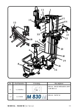
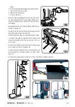
Page 37: ...M 830 LL M 830 M User Manual 123 A B C 1 2 D 17...

Page 38: ...124 M 830 LL M 830 M User Manual A B C D 1 2 2 18...

Page 39: ...e Fig 19 19 6 5 BEAD BREAKING Bead breaking is well known to be a dangerous operation It must be carried out in accordance with the instructions below WARNING Positioning the bead breaker Move the bea...

Page 40: ...distance is reached agapof2 3 mmshouldbe leftbetweenthe edge of the rim and the bead breaker disc operatethecon trol 2 fig 20d to prevent fur ther horizontal movement Breaking the top bead Preload the...

Page 41: ...calittle at a time using control 2 Fig 21 Perform at least one com pleterevolutiontobreakthe bead The rim bead should be greased during rotation Releasethepenetrationcon trol 1 Fig 21 Tilting the bead...

Page 42: ...tyre with the disc using control 1 Fig 23a The tyre should be pressed down by about 5 mm Obtain disc penetration by keeping button 2 Fig 23b pressed start to rotate the wheel 3 Fig 23b and at the sam...

Page 43: ...t Move the bead breaker unit from the working position to therestpositionbyusingthe handle 3 fig 24a Pressthebutton 1 Fig 24b and guide the bead breaker unit during rotation through 180 until it engag...

Page 44: ...ositioning the insert 3 Fig 25c must be against the edge of the rim in the point where the vertical wall starts Press the block 2 Fig 25c to fix the tool position Engaging the top bead Maintaining the...

Page 45: ...prepareforthe subsequent demounting This must be done with the wheel at a standstill and not rotating WARNING During demounting if the tool is unable to completely overturn the tyre bead to allow demo...

Page 46: ...o raise the tyre Otherwise to speed up the procedure simply place the PTS accessory between the tyre and the edge of the rim This will allow the bead to be lifted quickly off the rim so that it can be...

Page 47: ...ges with the tyre is normal The noise is made by the mechanical return of the tool and not because the tool has hit the rim Even if the tool does touch the rim as the tyre is engaged this will not dam...

Page 48: ...29b Rotate until the tyre is completely demounted Demounting the bottom bead fig 30 For reverse rims the disc stroke range can be increased by turning the bead breaker and tipping the disc over 3 4 F...

Page 49: ...M 830 LL M 830 M User Manual 135 1 2 3 4 30...

Page 50: ...rim and geometrical size keying diameter cross section width Off Set and shoulder profile before mounting AVOID PERSONAL INJURY OR DEATH Also check that rims are not deformed that their fixing holes...

Page 51: ...rol 1 Fig 33 to move the tool head into the working position The tool is already in the correct posi tion for mounting the tyre unless the type of rim has been changed Mounting the bot tom bead Fig 34...

Page 52: ...d Fig 35 Position the top bead of the tyre as clearly shown in fig 35 Take care that the tyre does not slip underneath the tool NOTICE Tilting the bead breaker unit fig 36 Press the button 1 Fig 36 an...

Page 53: ...he clamp to be inserted Mounting the top bead Fit the clamp 1 Fig 39a in the space created by the bead breaker disc Start rotation 2 Fig 39b to mount the bead until the clamp is close to the tool For...

Page 54: ...2 Fig 39d until the clamp 1 Fig 39d is close to the bead breaker disc and remove the clamp When mounting is complete raise the bead breaker disc using control 5 Fig 39d 5 1 2 39d Bring the bead breake...

Page 55: ...ariantofthenormalprocedure The first bead is mounted in the usual way To mount the second bead position the mobile tool as during the demounting search stage fig 41b This reduces the stresses leaving...

Page 56: ...ove the gripper to 2 o clock Positionthedemountingunit toolhead Lower the swing tool to find the bead Rotate clockwise so that the gripper is at 6 o clock sensor at 10 o clock The bead is now engaged...

Page 57: ...INFLATION 6 11 a SAFETY INDICATIONS The use of inflation devices e g guns connected to power sources outside of the machine is not permitted DANGER Always comply with national safety regulations as t...

Page 58: ...e on a 16 5 rim or vice versa This is very dangerous A mismatched tyre and rim could explode resulting in an accident 3 Never exceed the bead setting pressure gauge on hose pro videdbythetyremanufactu...

Page 59: ...r hose Doyfe inflator chuck to the valve stem 2 Fig 43c 2 3 4 5 43c Press toinflatethetyre Thetyrewillexpand and the beads will seat If necessary 6 Continue inflating up to the maximum value of 3 5 ba...

Page 60: ...hat there is no dirt dust or other impurities on the jaws near the air outlet holes If during inflation the tyre does not seat on the rim because of the excessive gap be tween the tyre rim it is possi...

Page 61: ...hrough the four jets to assist in seating the beads of the tyre Fig 44e 44d 44e To increase the effectiveness of the inflation jets always liberally lubricate beads and raise the lower bead while acti...

Page 62: ...ts towards people Bleed air pressure from system before disconnecting supply line or other pneumatic components Air is stored in a reservoir for operation of inflation jets Only activate the air infla...

Page 63: ...way from the rim by hand Fig 45b C Turn the clamping device anti clockwise to release it from the turntable Fig 45c D Remove the device from the rim Fig 45d Unloading the tyre Fig 46 A Lift the wheel...

Page 64: ...ck the wiring Motor shorted Renew the motor Replace motor inverter unit circuit board Check pedal unit microswitch Belt broken Replace belt Rotation control pedal fails to return to the central positi...

Page 65: ...ecalibrate The vertical slide has difficulty rising Defective clamping plate Renew plate Clamping plate not adjusted Adjust plate Vertical and horizontal limit stops do not operate No air passing thro...

Page 66: ...cylinder gasket Replace cylinder 8 MAINTENANCE For M 830 M see also the manual 4 119892 to integration NOTICE Any operation intended to modify the setting valve of the relief valve or pressure limite...

Page 67: ...operation or topping up with lubricant disconnect the machine from the compressed air supply line To increase the effectiveness of the inflation jets always liberally lubricate beads and raise the lo...

Page 68: ...time fig 47d Normally the cups do not need to be removed but check if this is necessary for mainte nance operations after a long period of use If a manual operation is not sufficient use the specific...

Page 69: ...tion of the country where the product is scrapped We also recommend you to adopt more measures for environment protection recycling of the internal and external packaging of the product and proper dis...

Page 70: ...e of exposure to strong concentration of vapours or mists take the affected person out into the open air and then to Casualty Eyes rinse with plenty of water and go to Casualty as soon as possible Ski...

Page 71: ...the structure its name The following structures are possible Conventional the plys are inclined and arranged so that the strands comprising a ply overlap with those of the adjacent ply The tread which...

Page 72: ...he casing to secure the ply and prevent it from slipping 12 Foot This is the innermost layer of the tread in contact with the belt or if the latter is not present conventional tyre with the last casin...

Page 73: ...surised air Valve The valve is a mechanical device to inflate deflate the tyre and maintain air pressure inside the air chamber or tyre in the case of tubeless tyres It consists of three parts the val...

Page 74: ...0 M 830 LL M 830 M User Manual Closed centre rim E Pick up rim D Reversed rim C Standard rim A Dropped centre hole rim B TABLEFORUSINGCENTRINGANDCLAMPING ACCESSORIESACCORDINGTORIMTYPE Open centre rim...

Page 75: ...LL M 830 M User Manual 161 M9 M2 M15 M4 M10 M13 M14 M7 M11 I Accessori a richiesta GB Accessories on request F Accessoires sur demande D Zubeh r auf Anfrage E Accessorios opcionales M16 CLAMPING ACCES...

Page 76: ...162 M 830 LL M 830 M User Manual M13 M14 M11 M7 M2 M9 A M16 STANDARD RIM...

Page 77: ...M 830 LL M 830 M User Manual 163 M6 M5 M11 M7 M9 B M16 DROPPED CENTRE HOLE RIM...

Page 78: ...164 M 830 LL M 830 M User Manual C M11 M2 REVERSED RIM...

Page 79: ...M 830 LL M 830 M User Manual 165 D M10 M2 M15 M9 PICK UP RIM...

Page 80: ...166 M 830 LL M 830 M User Manual E CLOSED CENTRE RIM...

Page 81: ...M 830 LL M 830 M User Manual 167 F OPEN CENTRE RIM...

Page 82: ...ser Manual ELECTRICAL DIAGRAM Table N 4 104805A Fig 48 AP1 Single two speed motor circuit board M1 Motor SQ1 Two speed microswitch SQ2 Microswitch CLOCKWISE rotation SQ3 Microswitch ANTI CLOCKWISE rot...

Page 83: ...CYLINDER CONTROL 8 Valve 3 2 NC 9 Release cylinder E COLUMN TILTING CYLINDER CONTROL 10 Valve 5 2 NO 11 Tilting cylinder F TOOL DRIVE CYLINDER CONTROL 12 Valve 5 2 NO 13 Tool drive cylinder G PEDAL UN...

Page 84: ...170 M 830 LL M 830 M User Manual...

Page 85: ...M 830 LL M 830 M User Manual 171 49...

Page 86: ...172 M 830 LL M 830 M User Manual Note...

Page 87: ...M 830 LL M 830 M User Manual 173 Note...

Reviews:

Related manuals for M 830 LL