B 215 / B 225 Evo
Operator’s manual
95
UK
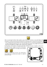
is equal to zero, the wheel is stopped in the inner side weight application position.
By simultaneously pressing
and
, automatic search for the second side
position is activated.
This function is described at length in the AUTOMATIC POSITION SEARCH section.
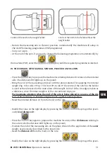
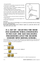
• Manually applied adhesive weights
- Select the first side to be balanced.
- Turn the wheel until the central element of the corresponding position indicator lights
up.
- Apply the indicated balancing weight in the position of the rim corresponding to 12
o'clock.
WARNING
The application position of the adhesive weight can be changed from 12 o'clock to 6 o'clock
by following the instructions in the set up menu “Adhesive weight application position ”.
WARNING
- for applying the adhesive weight in the MOTORCYCLE (ALU) programmes, always use
12 o'clock as the reference regardless of the setting in “SELECTION OF ADHESIVE
WEIGHT APPLICATION POSITION”.
IMPORTANT
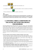
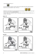
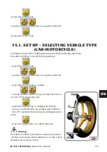
in ALU1 and ALU2 programmes the unbalance displayed by the machine on the outer side
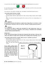
refers to the adhesive weight centre of gravity at the swinging unit bearing flange, (Fig. 17)
• Manually applied adhesive weights with laser device enabled (if provided)
- Select the first side to be balanced.
- Turn the wheel until the central element of the corresponding position indicator lights
up together with the laser line.
- Apply the indicated balancing weight in the position on the rim corresponding to 6
o'clock.
Some slight residual unbal-
ances may remain at the end of
the test spin due to the consid-
erable difference in shape that
may be found on rims having
the same rated dimensions.
Therefore modify the value and
position the previously applied
weights for accurate wheel
balancing.
17

