B 215 / B 225 Evo
Operator’s manual
73
UK
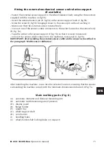
Fitting the external mechanical sensor and relative support
(if available)
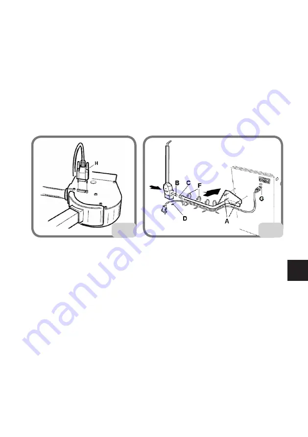
- Fasten the external sensor support to the wheel balancer body using the three screws
supplied with the machine (A, fig.5b);
- Insert the external sensor pin (B, fig.5b) in the sensor support bush (C, fig.5b);
- Screw the screw (D, fig.5b) bringing it closer to the sensor pin without touching it;
- Make sure that the external sensor rotates freely;
- Connect one of the sensor's cable connectors to the socket located on the sensor body
(H, fig. 5a);
- Tape the cable to the sensor support (F, fig. 5b) so that it is never tensioned;
- Connect the sensor cable connector to the machine's rear panel (G, fig.5b).
IMPORTANT: after installing the external sensor, calibrate the sensor as described in
the paragraph “Width sensor calibration”.
5a
5b
After installing the machine, move into the selected location, ensuring that the spaces
surrounding the machine comply with the minimum dimensions indicated in Fig. 5a.
Main working parts (Fig. 8)
(A) automatic diameter and distance measuring arm
(B) automatic width measuring arm (if present)
(D) display panel
(E) flange holder
(F) weight tray
(G) wheel support shaft
(H) cone holder
(I) handling holes
(L) wheel-holder shaft locking brake (on request)


