background image

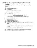
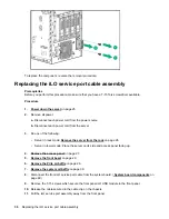
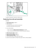
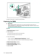
CAUTION:

To prevent damage to electrical components, properly ground the server before beginning any
installation procedure. Improper grounding can cause electrostatic discharge.

Procedure

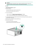
1. Power down the server 

on page 25.

2.

Remove all power:

a.

Disconnect each power cord from the power source.

b.

Disconnect each power cord from the server.

3.

Do one of the following:

• Server in rack mode: 

Remove the server from the rack

 on page 26.

• Server in tower mode: Place the server on its side and access panel facing up.

4.

If a Kensington security cable is installed, disconnect it from the rear panel. See the security cable
documentation for instructions.

5.

Place the server on its side and access panel facing up.

6.

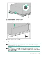
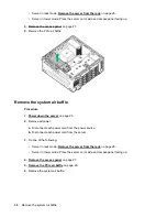
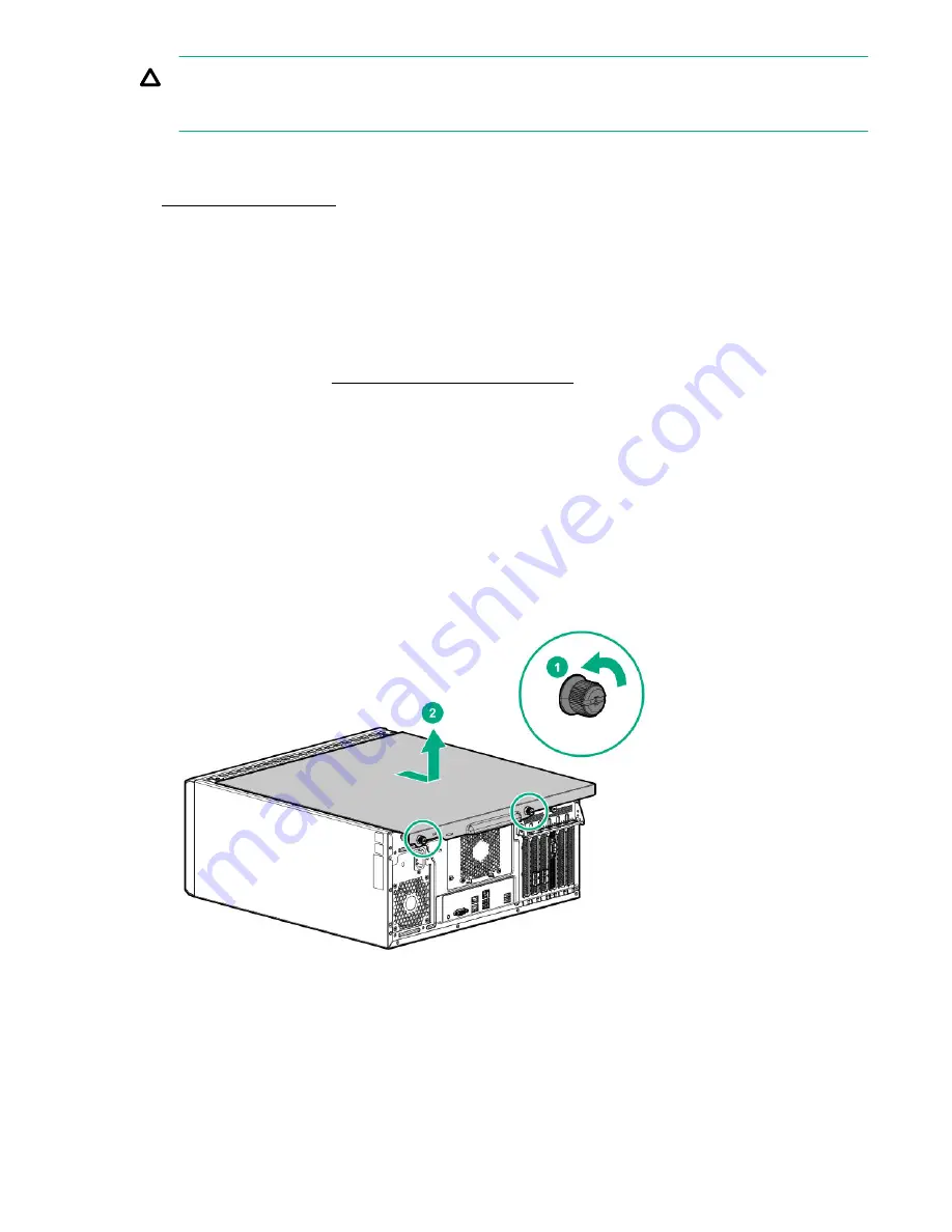
Remove the access panel:

a.

Loosen the access panel thumbscrews.

b.

Slide and remove the access panel from the server.

28

Removal and replacement procedures

Summary of Contents for ProLiant ML110 Gen10

Page 1: ...ion and maintenance procedures diagnostic tools specifications and requirements for hardware components and software This guide is for an experienced service technician Hewlett Packard Enterprise assumes that you are qualified in the servicing of computer equipment trained in recognizing hazards in products and are familiar with weight and stability precautions ...

Page 2: ...uired for possession use or copying Consistent with FAR 12 211 and 12 212 Commercial Computer Software Computer Software Documentation and Technical Data for Commercial Items are licensed to the U S Government under vendor s standard commercial license Links to third party websites take you outside the Hewlett Packard Enterprise website Hewlett Packard Enterprise has no control over and is not res...

Page 3: ...1 Four bay LFF drive cage backplane spare part 21 Eight bay SFF drive cage assembly spare part 22 Smart storage battery spare part 22 HPE Trusted Platform Module 2 0 spare part 22 Cable spare parts 22 Removal and replacement procedures 23 Safety considerations 23 Electrostatic discharge 23 Preventing electrostatic discharge 23 Grounding methods to prevent electrostatic discharge 23 Symbols on equi...

Page 4: ...placing the redundant PCIe fan module 51 Replacing the redundant system fan module 52 System battery information 53 Replacing the system battery 53 Replacing the smart storage battery 54 Replacing the system board assembly 55 Re entering the server serial number and product ID 57 HPE Trusted Platform Module 2 0 Gen10 Option 57 Troubleshooting 58 Troubleshooting resources 58 Diagnostic tools 59 Pro...

Page 5: ... supply cabling 90 Specifications 93 Environmental specifications 93 Server specifications 93 Power supply specifications 94 ATX 350W non hot plug power supply 94 ATX 550W non hot plug power supply 94 HPE 800W Flex Slot Platinum Hot Plug Low Halogen Power Supply 95 Hot plug power supply calculations 96 Safety warranty and regulatory information 97 Safety and regulatory compliance 97 Warranty infor...

Page 6: ...ifies in the materials shipped with a replacement CSR part whether a defective part must be returned to Hewlett Packard Enterprise In cases where it is required to return the defective part to Hewlett Packard Enterprise you must ship the defective part back to Hewlett Packard Enterprise within a defined period of time normally five 5 business days The defective part must be returned with the assoc...

Page 7: ...a société de courses ou le transporteur à utiliser Pour plus d informations sur le programme CSR de Hewlett Packard Enterprise contactez votre Mainteneur Agrée local Pour plus d informations sur ce programme en Amérique du Nord consultez le site Web Hewlett Packard Enterprise Service de garantie pièces seules Votre garantie limitée Hewlett Packard Enterprise peut inclure un service de garantie piè...

Page 8: ...aturzeiten zu minimieren und höhere Flexibilität beim Austausch defekter Bauteile zu ermöglichen Wenn Hewlett Packard Enterprise oder ein Hewlett Packard Enterprise Servicepartner bei der Diagnose feststellt dass das Produkt mithilfe eines CSR Teils repariert werden kann sendet Ihnen Hewlett Packard Enterprise dieses Bauteil zum Austausch direkt zu CSR Teile werden in zwei Kategorien unterteilt Zw...

Page 9: ...stos componentes también están diseñados para que puedan ser reparados por el usuario Sin embargo si precisa que Hewlett Packard Enterprise realice su sustitución puede o no conllevar costes adicionales dependiendo del tipo de servicio de garantía correspondiente al producto NOTA Algunos componentes de Hewlett Packard Enterprise no están diseñados para que puedan ser reparados por el usuario Para ...

Page 10: ...tt Packard Enterprise onderdelen zijn niet ontwikkeld voor reparatie door de klant In verband met de garantievoorwaarden moet het onderdeel door een geautoriseerde Service Partner worden vervangen Deze onderdelen worden in de geïllustreerde onderdelencatalogus aangemerkt met Nee Afhankelijk van de leverbaarheid en de locatie worden CSR onderdelen verzonden voor levering op de eerstvolgende werkdag...

Page 11: ...viadas no primeiro dia útil após o pedido Onde as condições geográficas permitirem a entrega no mesmo dia ou em quatro horas pode ser feita mediante uma taxa adicional Se precisar de auxílio entre em contato com o Centro de suporte técnico da Hewlett Packard Enterprise para que um técnico o ajude por telefone A Hewlett Packard Enterprise especifica nos materiais fornecidos com a peça CSR de reposi...

Page 12: ...12 Customer self repair ...

Page 13: ...Customer self repair 13 ...

Page 14: ...14 Customer self repair ...

Page 15: ...Customer self repair 15 ...

Page 16: ...e Hewlett Packard Enterprise PartSurfer website http www hpe com info partssurfer Item Description 1 Redundant power supply blank spare part 2 SFF drive blank spare part 3 LFF drive blank spare part 4 Four bay LFF non hot plug drive cage spare part 5 PCIe air baffle spare part Redundant power supply blank spare part Customer self repair on page 6 Mandatory Description Spare part number Redundant p...

Page 17: ...are part Customer self repair on page 6 Mandatory Description Spare part number Four bay LFF non hot plug drive cage 792353 001 PCIe air baffle spare part Customer self repair on page 6 Mandatory Description Spare part number PCIe air baffle 791709 001 System components Hewlett Packard Enterprise continually improves and changes product parts For complete and current supported spare parts informat...

Page 18: ... fan module spare part 1 6 System battery spare part 7 System board spare part 8 DIMM spare part 9 Heatsink spare part 10 Processor spare part 11 Redundant system fan spare part 1 12 System fan spare part 1 Same module is used for both system and PCIe redundant fan options Hot plug power supply spare part Customer self repair on page 6 Mandatory 18 Hot plug power supply spare part ...

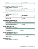
Page 19: ... 350 W power supply 878924 001 550 W power supply 878923 001 Redundant fan module spare part Customer self repair on page 6 Mandatory Description Spare part number Redundant fan module system and PCIe 878927 001 System battery spare part Customer self repair on page 6 Mandatory Description Spare part number 3 V lithium battery coin 319603 001 System board assembly spare part Customer self repair o...

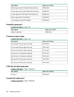
Page 20: ...re parts Customer self repair on page 6 No Description Spare part number Intel Xeon B 3104 processor assembly 875709 001 Intel Xeon B 3106 processor assembly 875710 001 Intel Xeon S 4108 processor assembly 875712 001 Intel Xeon S 4110 processor assembly 875711 001 Intel Xeon S 4112 processor assembly 875714 001 Intel Xeon G 5120 processor assembly 875718 001 Intel Xeon G 5122 processor assembly 87...

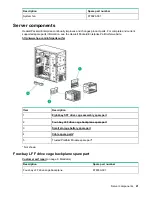
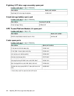
Page 21: ...Surfer website http www hpe com info partssurfer Item Description 1 Eight bay SFF drive cage assembly spare part 2 Four bay LFF drive cage backplane spare part 3 Smart storage battery spare part 4 Cable spare parts 5 Trusted Platform Module spare part Not shown Four bay LFF drive cage backplane spare part Customer self repair on page 6 Mandatory Description Spare part number Four bay LFF drive cag...

Page 22: ... part number HPE Trusted Platform Module Gen10 TAA 872159 001 Cable spare parts Customer self repair on page 6 Mandatory Description Spare part number Front panel LED cable assembly 878931 001 Front USB 3 0 ports cable assembly 878932 001 iLO service port cable assembly 878933 001 Serial port cable assembly 879778 001 Hot plug four bay LFF SFF drive mini SAS cable1 878327 001 Non hot plug SATA to ...

Page 23: ...ic sensitive component or assembly Grounding methods to prevent electrostatic discharge Several methods are used for grounding Use one or more of the following methods when handling or installing electrostatic sensitive parts Use a wrist strap connected by a ground cord to a grounded workstation or computer chassis Wrist straps are flexible straps with a minimum of 1 megohm 10 percent resistance i...

Page 24: ...njury from a hot component allow the surface to cool before touching This symbol indicates that the component exceeds the recommended weight for one individual to handle safely WARNING To reduce the risk of personal injury or damage to the equipment observe local occupational health and safety requirements and guidelines for manual material handling These symbols on power supplies or systems indic...

Page 25: ...ack up all server data before installing or removing a hardware option or performing a server maintenance or troubleshooting procedure Required tools You need the following items for some procedures T 10 Torx screwdriver T 15 Torx screwdriver Preparation procedures To access some components and perform certain service procedures you must perform one or more of the following procedures Procedure Po...

Page 26: ...erver is in standby mode by observing that the system power LED is amber Remove the server from the rack WARNING This server is heavy To reduce the risk of personal injury or damage to the equipment Observe local occupational health and safety requirements and guidelines for manual material handling Get help to lift and stabilize the product during installation or removal especially when the produ...

Page 27: ...l WARNING To reduce the risk of personal injury from hot surfaces allow the drives and the internal system components to cool before touching them CAUTION For proper cooling do not operate the server without the access panel baffles expansion slot covers or blanks installed If the server supports hot plug components minimize the amount of time the access panel is open Remove the access panel 27 ...

Page 28: ...m the server 3 Do one of the following Server in rack mode Remove the server from the rack on page 26 Server in tower mode Place the server on its side and access panel facing up 4 If a Kensington security cable is installed disconnect it from the rear panel See the security cable documentation for instructions 5 Place the server on its side and access panel facing up 6 Remove the access panel a L...

Page 29: ...el facing up 4 If the front bezel is locked by the internal locker remove the access panel 5 Open and remove the front bezel a Slide up the internal locker b Open the front bezel c Remove the front bezel Remove the PCIe air baffle Procedure 1 Power down the server on page 25 2 Remove all power a Disconnect each power cord from the power source b Disconnect each power cord from the server 3 Do one ...

Page 30: ...wer down the server on page 25 2 Remove all power a Disconnect each power cord from the power source b Disconnect each power cord from the server 3 Do one of the following Server in rack mode Remove the server from the rack on page 26 Server in tower mode Place the server on its side and access panel facing up 4 Remove the access panel on page 27 5 Remove the PCIe air baffle on page 29 6 Remove th...

Page 31: ... the server unless all bays are populated with either a component or a blank Removing and replacing an LFF drive blank Procedure 1 Remove the front bezel on page 29 2 Remove the drive blank 3 To replace the blank slide the blank into the bay until it locks into place Removing and replacing a drive blank 31 ...

Page 32: ...cing the hot plug drive CAUTION To prevent improper cooling and thermal damage do not operate the server unless all bays are populated with either a component or a blank Procedure 1 Remove the front bezel on page 29 2 Back up all server data on the drive 3 Determine the status of the drive from the drive LED definitions 4 Remove the drive To replace the component reverse the removal procedure 32 R...

Page 33: ... the following Server in rack mode Remove the server from the rack on page 26 Server in tower mode Place the server on its side and access panel facing up 4 Remove the access panel on page 27 5 Remove the front bezel on page 29 6 Remove the PCIe air baffle on page 29 7 Remove the system air baffle on page 30 8 Disconnect all existing drive cables 9 Remove the non hot plug drive cage 10 Remove the ...

Page 34: ...rack on page 26 Server in tower mode Place the server on its side and access panel facing up 4 Remove the access panel on page 27 5 Remove the front bezel on page 29 6 Remove the PCIe air baffle on page 29 7 Remove the system air baffle on page 30 8 Disconnect the front I O cable from the system board System board components on page 69 9 Remove the T 15 screw which secures the front panel LED modu...

Page 35: ...cing up 4 Remove the access panel on page 27 5 Remove the front bezel on page 29 6 Remove the PCIe air baffle on page 29 7 Remove the system air baffle on page 30 8 Disconnect the front USB 3 0 ports cable from the system board System board components on page 69 a Press the latch on the connector b Pull out the cable from the connector to avoid damaging the connector by pulling up the cable vertic...

Page 36: ...rver from the rack on page 26 Server in tower mode Place the server on its side and access panel facing up 4 Remove the access panel on page 27 5 Remove the front bezel on page 29 6 Remove the PCIe air baffle on page 29 7 Remove the system air baffle on page 30 8 Disconnect the front iLO service port cable from the system board System board components on page 69 9 Remove the T 15 screws which secu...

Page 37: ... of the following Server in rack mode Remove the server from the rack on page 26 Server in tower mode Place the server on its side and access panel facing up 4 Remove the access panel on page 27 5 Remove the PCIe air baffle on page 29 6 Remove the system air baffle on page 30 7 Loosen the thumbscrew and open the slot cover retainer 8 Disconnect the serial cable from the system board and remove the...

Page 38: ...ng components Procedure 1 Power down the server on page 25 2 Remove all power a Disconnect each power cord from the power source b Disconnect each power cord from the server 3 Do one of the following Server in rack mode Remove the server from the rack on page 26 Server in tower mode Place the server on its side and access panel facing up 4 Remove the access panel on page 27 5 Remove the PCIe air b...

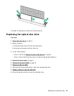
Page 39: ...ollowing Server in rack mode Remove the server from the rack on page 26 Server in tower mode Place the server on its side and access panel facing up 4 Remove the access panel on page 27 5 Remove the system air baffle on page 30 6 Remove the PCIe air baffle 7 Disconnect the power and the SATA Y cable from the optical disc drive 8 Release cables from clip and metal tabs 9 Press the metal tab and the...

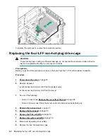
Page 40: ...own the server on page 25 2 Remove all power a Disconnect each power cord from the power source b Disconnect each power cord from the server 3 Do one of the following Server in rack mode Remove the server from the rack on page 26 Server in tower mode Place the server on its side and access panel facing up 4 Remove the access panel on page 27 5 Remove the front bezel on page 29 6 Remove the PCIe ai...

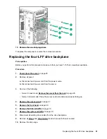
Page 41: ...ect each power cord from the server 3 Do one of the following Server in rack mode Remove the server from the rack on page 26 Server in tower mode Place the server on its side and access panel facing up 4 Remove the access panel on page 27 5 Remove the front bezel on page 29 6 Remove the PCIe air baffle on page 29 7 Remove the system air baffle on page 30 8 Disconnect all existing drive cables from...

Page 42: ...val procedure Replacing the eight SFF drive cage assembly Prerequisites Before you perform this procedure make sure that you have T 15 Torx screwdriver available Procedure 1 Power down the server on page 25 2 Remove all power 42 Replacing the eight SFF drive cage assembly ...

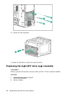
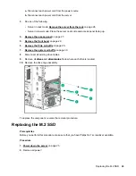
Page 43: ...nt bezel on page 29 6 Remove the PCIe air baffle on page 29 7 Remove the system air baffle on page 30 8 Disconnect all existing drive cables 9 Remove all drives and drive blanks Note where each drive is located 10 Remove the drive cage assembly To replace the component reverse the removal procedure Replacing the M 2 SSD Prerequisites Before you perform this procedure make sure that you have Philip...

Page 44: ... server from the rack on page 26 Server in tower mode Place the server on its side and access panel facing up 4 Remove the access panel on page 27 5 Remove the PCIe air baffle on page 29 6 Remove the system air baffle on page 30 7 Disconnect the SATA cable 8 Remove the M 2 SSD enablement board 9 Remove the M 2 SSD 44 Removal and replacement procedures ...

Page 45: ...ct each power cord from the server 3 Do one of the following Server in rack mode Remove the server from the rack on page 26 Server in tower mode Place the server on its side and access panel facing up 4 Remove the access panel on page 27 5 Remove the PCIe air baffle on page 29 6 Remove the system air baffle on page 30 7 Disconnect all power supply cables from the system board drive cages and devic...

Page 46: ...either a component or a blank To replace the component reverse the removal procedure Replacing the hot plug power supply Procedure 1 Power down the server on page 25 2 Remove all power a Disconnect each power cord from the power source b Disconnect each power cord from the server 3 Release the strain relief strap 46 Removing the power supply blank ...

Page 47: ...quisites Before you perform this procedure make sure that you have T 15 Torx screwdriver available Procedure 1 Power down the server on page 25 2 Remove all power a Disconnect each power cord from the power source b Disconnect each power cord from the server 3 Do one of the following Replacing the redundant power supply backplane module 47 ...

Page 48: ... on page 27 5 Remove the PCIe air baffle on page 29 6 Remove the system air baffle on page 30 7 If installed remove the power input module 8 Disconnect all the backplane cables 9 Remove the RPS backplane assembly from the bay 10 Detach the RPS bracket from the RPS backplane To replace the component reverse the removal procedure 48 Removal and replacement procedures ...

Page 49: ... from the server 3 Do one of the following Server in rack mode Remove the server from the rack on page 26 Server in tower mode Place the server on its side and access panel facing up 4 Remove the access panel on page 27 5 Remove the PCIe air baffle on page 29 6 Remove the system air baffle on page 30 7 Disconnect all fan cables from the system board 8 Remove the cables from the cable clip 9 Remove...

Page 50: ...the server 3 Do one of the following Server in rack mode Remove the server from the rack on page 26 Server in tower mode Place the server on its side and access panel facing up 4 Remove the access panel on page 27 5 Remove the PCIe air baffle on page 29 6 Remove the system air baffle on page 30 7 Disconnect the fan cable 8 Remove the fan cable from the cable clip and then remove the system fan To ...

Page 51: ... from the server 3 Do one of the following Server in rack mode Remove the server from the rack on page 26 Server in tower mode Place the server on its side and access panel facing up 4 Remove the access panel on page 27 5 Remove the PCIe air baffle on page 29 6 Remove the system air baffle on page 30 7 Disconnect all fan cables from the system board 8 Remove the cables from the cable clip 9 Remove...

Page 52: ...3 Do one of the following Server in rack mode Remove the server from the rack on page 26 Server in tower mode Place the server on its side and access panel facing up 4 Remove the access panel on page 27 5 Remove the PCIe air baffle on page 29 6 Remove the system air baffle on page 30 7 Disconnect all fan cables from the system board 8 Remove the cables from the cable clip 9 Remove the redundant fa...

Page 53: ...e and time then replace the battery that provides power to the real time clock Under normal use battery life is 5 to 10 years Replacing the system battery Procedure 1 Power down the server on page 25 2 Remove all power a Disconnect each power cord from the power source b Disconnect each power cord from the server 3 Do one of the following Server in rack mode Remove the server from the rack on page...

Page 54: ...from the server 3 Do one of the following Server in rack mode Remove the server from the rack on page 26 Server in tower mode Place the server on its side and access panel facing up 4 Remove the access panel on page 27 5 Remove the PCIe air baffle on page 29 6 Remove the system air baffle on page 30 7 Disconnect the battery cable from the system board connector 8 Remove the Smart Storage Battery 5...

Page 55: ... from the server 3 Do one of the following Server in rack mode Remove the server from the rack on page 26 Server in tower mode Place the server on its side and access panel facing up 4 Remove the access panel on page 27 5 Remove the PCIe air baffle on page 29 6 Remove the system air baffle on page 30 7 Disconnect all cables connected to the system board assembly 8 If installed remove all the PCIe ...

Page 56: ...e order specified by the label on the heatsink c Lift the processor heatsink assembly and move it away from the system board d Turn the assembly over and place it on a work surface with the processor facing up e Install the dust cover 15 Loosen the screws on the system board 16 Remove the system board To replace the component reverse the removal procedure 56 Removal and replacement procedures ...

Page 57: ...r key 6 Select Product ID The following warning appears Warning The Product ID should ONLY be modified by qualified service personnel This value should always match the Product ID located on the chassis 7 Enter the product ID and press the Enter key 8 To confirm exiting System Utilities press the F10 key The server automatically reboots HPE Trusted Platform Module 2 0 Gen10 Option The HPE Trusted ...

Page 58: ...ntenance Error Message Guide for HPE ProLiant Gen10 servers and HPE Synergy provides a list of error messages and information to assist with interpreting and resolving error messages Integrated Management Log Messages and Troubleshooting Guide for HPE ProLiant Gen10 and HPE Synergy provides IML messages and associated troubleshooting information to resolve critical and cautionary IML events To acc...

Page 59: ...cure Boot that enables the system firmware option card firmware operating systems and software collaborate to enhance platform security UEFI Graphical User Interface GUI An Embedded UEFI Shell that provides a preboot environment for running scripts and tools Boot support for option cards that only support a UEFI option ROM Selecting the boot mode This server provides two Boot Mode configurations U...

Page 60: ... and operating systems with boot loaders must have an appropriate digital signature to execute during the boot process Operating systems must support Secure Boot and have an EFI boot loader signed with one of the authorized keys to boot For more information about supported operating systems see http www hpe com servers ossupport You can customize the certificates embedded in the UEFI BIOS by addin...

Page 61: ...nsed vendor media and Hewlett Packard Enterprise branded versions of OS software Intelligent Provisioning also prepares the system to integrate optimized server support software from the Service Pack for ProLiant SPP SPP is a comprehensive systems software and firmware solution for ProLiant servers server blades their enclosures and HPE Synergy compute modules These components are preloaded with a...

Page 62: ... operating system see the OS Support Matrix on the Hewlett Packard Enterprise website http www hpe com info ossupport HPE Insight Remote Support Hewlett Packard Enterprise strongly recommends that you register your device for remote support to enable enhanced delivery of your Hewlett Packard Enterprise warranty HPE support services or Hewlett Packard Enterprise contractual support agreement Insigh...

Page 63: ...s required to be configured before the operating system can be installed You can configure the array using SSA HPE SSA is accessible both offline either through HPE Intelligent Provisioning or as a standalone bootable ISO image and online Accessing HPE SSA in the offline environment IMPORTANT If you are updating an existing server in an offline environment obtain the latest version of HPE SSA thro...

Page 64: ...Component identification Front panel components Item Description 1 Box 2 2 Box 1 3 USB 3 0 connectors 4 iLO service port 5 PCIe Fan 6 Slim Optical Disc Drive Optional 64 Component identification ...

Page 65: ...nd is working correctly The power cord is attached and is connected to a power source The front I O cable is connected 2 Health LED Solid green Normal Flashing green 1 flash per second iLO is rebooting Flashing amber System degraded Flashing red 1 flash per second System critical1 3 NIC status LED Solid green Link to network Flashing green 1 flash per second Network active Off No network activity ...

Page 66: ...nel LEDs on page 68 Rear panel components Item Description 1 Non hot plug power supply 2 Kensington security slot 3 Padlock eye 4 Power supply bay 1 of the hot plug power supply optional 5 Power supply bay 2 of the hot plug power supply optional 6 NIC port 1 7 System fan 8 iLO Management port 9 Slot 5 PCIe3x8 4 1 10 Slot 4 PCIe3 x16 16 8 4 1 11 Serial port optional 12 Slot 3 PCIe3 x8 8 4 1 13 Slot...

Page 67: ...uide on the Hewlett Packard Enterprise website Power fault LEDs The following table provides a list of power fault LEDs and the subsystems that are affected Not all power faults are used by all servers Subsystem LED behavior System board 1 flash Processor 2 flashes Memory 3 flashes Removable HPE Flexible Smart Array controller Smart SAS HBA controller 6 flashes System board PCIe slots 7 flashes Po...

Page 68: ...navailable Power supply failed Power supply is in standby mode Power supply error 2 iLO link LED Green Linked to network connection Off No network connection 3 iLO activity LED Green or flashing green Network activity Off No network activity 4 NIC link LED Green Linked to network Off No network connection Table Continued 68 Rear panel LEDs ...

Page 69: ... 1 flash per second Remote management or firmware upgrade in progress 4 flashes per second iLO manual reboot sequence initiated 8 flashes per second iLO manual reboot sequence in progress Off Deactivated IMPORTANT Consider NIC as HPE Ethernet 1GB 2 port 332i Adapter whose performance is a PCIe Gen2 x1 device System board components System board components 69 ...

Page 70: ... iLO service port connector 12 Front USB 3 0 connector 13 SATA port 9 14 TPM connector 15 Fan connector 1 PCIe fan 16 Fan connector 2 PCIe fan 17 SATA port 10 18 Storage backup power connectors 19 microSD slot1 20 System maintenance switch 21 Smart storage battery connector 22 Internal USB 2 0 connector 23 Slot 5 PCIe3 x8 4 1 2 24 Serial port connector 25 Slot 4 PCIe3 x16 16 8 4 1 Table Continued ...

Page 71: ...n System configuration is locked S3 Off Reserved S4 Off Reserved S51 Off Off Power on password is enabled On Power on password is disabled S61 2 3 Off Off No function On Restore default manufacturing settings S7 Off Off Set default boot mode to UEFI On Set default boot mode to legacy S8 Reserved S9 Reserved S10 Reserved S11 Reserved S12 Reserved 1 To access the redundant ROM set S1 S5 and S6 to On...

Page 72: ...ly 1 through 6 for the processor The arrow points to the front of the server IMPORTANT A3DC only supports DIMM module with 32G dual rank Drives LFF drive LED definitions Item Definition 1 Fault UID amber blue 2 Online Activity green 72 DIMM slot locations ...

Page 73: ...ripe migration but a predictive failure alert has been received for this drive To minimize the risk of data loss do not remove the drive until the expansion or migration is complete 1 flash per second Off Do not remove the drive Removing the drive might terminate the current operation and cause data loss The drive is rebuilding erasing or is part of an array that is undergoing capacity expansion o...

Page 74: ...gical drive extension or is erasing Flashing amber green The drive is a member of one or more logical drives and predicts the drive will fail Flashing amber The drive is not configured and predicts the drive will fail Solid amber The drive has failed Off The drive is not configured by a RAID controller 4 Do not remove LED Solid white Do not remove the drive Removing the drive causes one or more of...

Page 75: ...drives 8 LFF hot plug drives or 16 SFF hot plug drives If only one drive cage is installed it must be installed in box 1 The server does not support mixing SFF and LFF drives Hewlett Packard Enterprise recommends that you populate drive bays starting with the lowest drive number Drives are numbered from left to right in each component box Four bay LFF non hot plug drive model Four bay LFF hot plug...

Page 76: ...Fan locations Item Description 1 Default system fan module 92 x 32 mm 2 Default PCIe fan module 92 X 32 mm The server also supports redundant fan options see Redundant fan option 76 Fan locations ...

Page 77: ...ace to verify the length of the cable Use the internal cable management features to properly route and secure the cables When routing cables be sure that the cables are not in a position where they can be pinched or crimped Avoid tight bend radii to prevent damaging the internal wires of a power cord or a server cable Never bend power cords and server cables tight enough to cause a crease in the s...

Page 78: ... If you intend to use the removed cables later label and store them for future use Drive and Storage cabling LFF non hot plug drive cabling Eight bay LFF non hot plug drive cabling Cable Color Description Orange Power supply cable Pink Power supply cable Table Continued 78 Drive and Storage cabling ...

Page 79: ...to system board x4 SATA port 2 Amber Box 1 non hot plug drive to system board x4 SATA port 1 LFF hot plug drive cabling Box 1 drive backplane connected to the system board Cable Color Description Orange Drive power supply cable Blue Box 1 drive backplane Mini SAS cable to system board x4 SATA port 1 LFF hot plug drive cabling 79 ...

Page 80: ...wer supply cable Blue Box 2 drive backplane Mini SAS cable to system board x4 SATA port 2 Box 1 and Box 2 drive backplanes connected to a HBA Smart Array controller Cable Color Description Orange Box 2 drive power supply cable Blue Box 1 drive power supply cable Table Continued 80 Cabling ...

Page 81: ...roller port 1 SFF hot plug drive cabling Box 1 drive backplane connected to the system board Cable color Description Orange Drive power supply cable Blue Box 1 drive backplane port 1 Mini SAS cable to system board x4 SATA port 1 Amber Box 1 drive backplane port 2 Mini SAS cable to system board x4 SATA port 2 SFF hot plug drive cabling 81 ...

Page 82: ...ay controller Item Description Orange Drive power supply cable Blue Box 1 drive backplane port 1 Mini SAS cable to type p controller port 1 Amber Box 1 drive backplane port 2 Mini SAS cable to type p controller port 2 M 2 SSD cabling 82 M 2 SSD cabling ...

Page 83: ...0 Storage controller cabling Host Bus Adapter Smart Array controller connected to the 2x 4 bay LFF hot plug drive cage Cable color Description Orange Box 1 drive backplane Mini SAS cable to type p controller port 1 Blue Box 2 drive backplane Mini SAS cable to type p controller port 2 Yellow Box 1 drive power supply cable Pink Box 2 drive power supply cable Storage controller cabling 83 ...

Page 84: ... controller port 1 Green Box 1 drive backplane port 2 Mini SAS cable to slot 2 type p controller port 2 Black Box 1 drive power supply cable Orange Box 2 drive power supply cable FBWC module cabling The FBWC solution is a separately purchased option This server only supports FBWC module installation when a Smart Array P Series controller is installed Depending on the controller option installed th...

Page 85: ...Smart Storage Battery cabling Smart Storage Battery cabling 85 ...

Page 86: ...Serial port cabling Front I O cabling 86 Serial port cabling ...

Page 87: ...Front USB 3 0 cabling iLO service port cabling Front USB 3 0 cabling 87 ...

Page 88: ...Optical drive cabling Cable color Description Orange Power supply cable Blue Drive power supply cable Amber SATA cable Fan cabling Default system fan cabling 88 Optical drive cabling ...

Page 89: ...Redundant system fan cabling Cable color Description Orange System fan cable to fan connector 4 Blue System fan cable to fan connector 3 Default PCIe fan cabling Cabling 89 ...

Page 90: ... Blue PCIe fan cable to fan connector 2 Power supply cabling 350W non hot plug power supply cabling Cable Color Description Orange 8 pin power supply cable to box 2 drive backplane Blue 8 pin power supply cable to box 1 drive backplane and optical drive Table Continued 90 Power supply cabling ...

Page 91: ...pply cable 550W non hot plug power supply cabling Cable Color Description Orange 8 pin power supply cable to box 2 drive backplane and optical drive Blue 8 pin power supply cable to box 1 drive backplane Amber 4 pin power supply cable to system board Pink 24 pin power supply cable Cabling 91 ...

Page 92: ... Cable Color Description Pink RPSU cable Blue Box 1 drive backplane power supply cable Amber 4 pin power supply cable to system board Orange Box 2 drive backplane and media bay power cable Green 24 pin power supply cable 92 Cabling ...

Page 93: ...talled For certain approved hardware configurations the supported system inlet temperature range is extended 5 C to 10 C 41 F to 50 F and 35 C to 40 C 95 F to 104 F at sea level with an altitude derating of 1 0 C per every 175 m 1 8 F per every 574 ft above 900 m 2953 ft to a maximum of 3050 m 10 000 ft A redundant fan is required when the ambient temperature reaches 35 C to 40 C The approved hard...

Page 94: ...t redundant fan option ATX 350W non hot plug power supply Specification Value Input requirements Rated input voltage 100 VAC to 240 VAC Rated input frequency 50 Hz to 60 Hz Rated input current 4 5 A at 100 VAC 1 9 A at 240 VAC Maximum rated input power 437 W at 100 VAC 416 W at 240 VAC BTUs per hour 1491 at 100 VAC 1419 at 240 VAC Power supply output Rated steady state power 350 W at 100VAC to 240...

Page 95: ...er Supply Specification Value Input requirements Rated input voltage 100 VAC to 127 VAC 100 VAC to 240 VAC 240 VDC for China only Rated input frequency 50 Hz to 60 Hz Not applicable to 240 VDC Rated input current 9 4 A at 100 VAC 4 5 A at 200 VAC 3 8 A at 240 VDC for China only Maximum rated input power 899 W at 100 VAC 867 W at 200 VAC 864 W at 240 VDC for China only BTUs per hour 3 067 at 100 VA...

Page 96: ...100 VAC to 127 VAC input 800 W at 100 VAC to 240 VAC input 800 W at 240 VDC input for China only Hot plug power supply calculations For hot plug power supply specifications and calculators to determine electrical and heat loading for the server see the Hewlett Packard Enterprise Power Advisor website http www hpe com info poweradvisor online 96 Hot plug power supply calculations ...

Page 97: ...fety Compliance EnterpriseProducts Warranty information HPE ProLiant and x86 Servers and Options HPE Enterprise Servers HPE Storage Products HPE Networking Products Belarus Kazakhstan Russia marking Manufacturer and Local Representative Information Manufacturer information Hewlett Packard Enterprise Company 3000 Hanover Street Palo Alto CA 94304 U S Local representative information Russian Russia ...

Page 98: ...w decade with 2000 as the starting point for example 238 2 for 2002 and 38 for the week of September 9 In addition 2010 is indicated by 0 2011 by 1 2012 by 2 2013 by 3 and so forth YYWW where YY indicates the year using a base year of 2000 for example 0238 02 for 2002 and 38 for the week of September 9 Turkey RoHS material content declaration Ukraine RoHS material content declaration 98 Turkey RoH...

Page 99: ...atibility matrix www hpe com storage spock Storage white papers and analyst reports www hpe com storage whitepapers For additional general support websites see Support and other resources Product websites Product QuickSpecs http www hpe com servers ml110 gen10 HPE ProLiant ML110 Gen10 support page http www hpe com support ml110gen10 HPE ProLiant ML110 Gen10 documents http www hpe com info ml110gen...

Page 100: ...rd party products or components Accessing updates Some software products provide a mechanism for accessing software updates through the product interface Review your product documentation to identify the recommended software update method To download product updates Hewlett Packard Enterprise Support Center www hpe com support hpesc Hewlett Packard Enterprise Support Center Software downloads www ...

Page 101: ...vel Hewlett Packard Enterprise strongly recommends that you register your device for remote support If your product includes additional remote support details use search to locate that information Remote support and Proactive Care information HPE Get Connected www hpe com services getconnected HPE Proactive Care services www hpe com services proactivecare HPE Proactive Care service Supported produ...

Reviews: