background image

Elliptical Cross

-

Trainer 

&

 Exercise Bike 


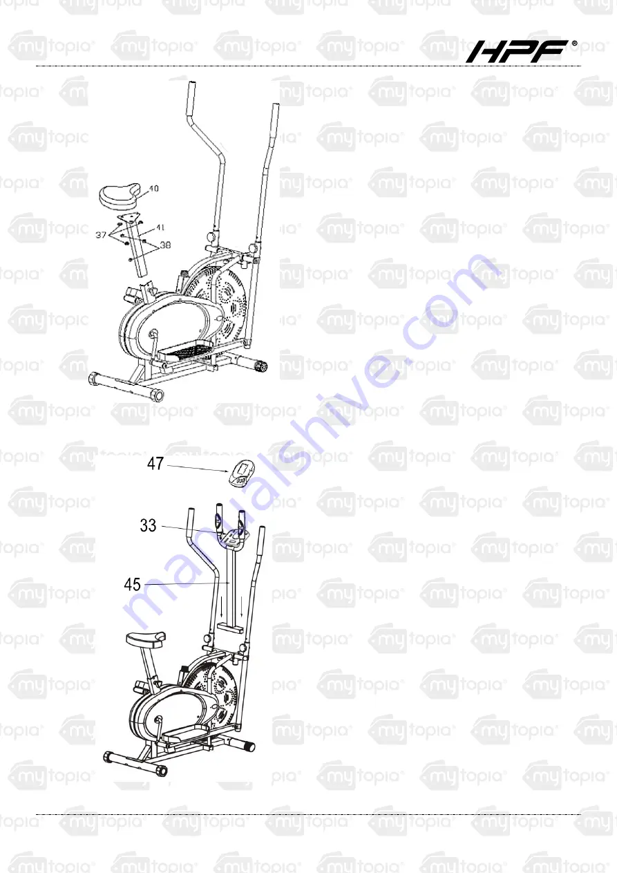
Figure 5 


Remove the washer (No. 37) and nut (No. 
38) from the saddle (No. 40).  Attach the 
saddle and saddle post (No. 41) as shown in 
Figure 5.  Re-insert and tighten the bolts. 


Put the plastic insert (No. 39) over the saddle 
post then insert the saddle post into the main 
frame as shown in Figure 5.  Insert and 
tighten the knob (No. 42). 


Figure 6 


Remove the screws and washers from the 
back of the meter monitor (No. 47) and put 
aside. 


Attach the monitor to the handlebar (No. 45) 
by inserting onto the meter bracket (No. 33) 
and feeding the wires through the large 
round opening. 


Secure the meter monitor with the screws 
and washers that had previously been 
removed, but screw into the upper threads. 


Connect the 3 wires on the meter monitor to 
the 3 wires on the handlebar, matching each 
with any connection that appropriately fits. 


Attach the handlebar to the cross-trainer by 
inserting it into the handlebar tubing holsters 
and securing with the locking knobs (No. 28). 


Connect the wire located at the bottom end 
of the handlebar with the wire located at the 
front of the main frame. 

Summary of Contents for FTNXTRHPFAXV3

Page 1: ...Elliptical Cross Trainer Exercise Bike User Manual RETAIN THIS MANUAL FOR FUTURE REFERENCE PLEASE READ THIS MANUAL CAREFULLY BEFORE USE ...

Page 2: ... of Contents SAFETY REMINDERS 1 EXPLODED DIAGRAM 2 PARTS LIST 4 ASSEMBLY INSTRUCTIONS 5 Preparation 5 Assembly 5 Reversible Movement 9 DISPLAY SCREEN 10 TROUBLESHOOTING 11 Changing the Batteries 11 Computer Not Working Correctly 11 No Resistance 11 ...

Page 3: ...cted by incorrect or excessive training Consult a doctor before beginning a training program The doctor can define the maximum setting pulse watts duration of training etc to which you may train yourself and can get precise information during training This machine is not suitable for therapeutic purpose 8 Only do training on the machine when it is in correctly working Use only original spare parts...

Page 4: ...Elliptical Cross Trainer Exercise Bike 2 Exploded Diagram ...

Page 5: ...Elliptical Cross Trainer Exercise Bike 3 ...

Page 6: ... 32 CONNECTING ROD FOR METER 1 9 LOWER HANDLE BAR RIGHT 1 33 METER BRACKET 1 10 LOWER HANDLE BAR LEFT 1 34 TENSION CONTROL 1 11 RIGHT PEDAL POST 1 35 CHAIN COVER 2 12 LEFT PEDAL POST 1 36 ARC WASHER 4 13 NUT M10 4 37 WASHER 3 14 BOLT 2 38 NUT M8 3 15 PEDAL HINGE BOLT L R 2 39 PLASTIC INSERT 1 16 STEEL BUSHING 8 40 SADDLE 1 17 NUT 1 2 L R 2 41 SADDLE POST 1 18 SPRING WASHER 2 42 KNOB 1 19 HINGE SCR...

Page 7: ...this equipment consists of Assembly Figure 1 Attach the Front Stabilizer No 7 and the Rear Stabilizer No 2 with four sets of Carriage Bolts N0 4 Washers No 6 and Domed Nuts No 5 N B The Front Stabilizer has the integral transport wheels Figure 2 Insert the Spindle Bar No 22 through the Right Lower Handlebar No 9 and through the main frame and then through the arc washer No 36 and the Left Handleba...

Page 8: ...nsure the wave washer and spring washer are correctly located Tighten the bolt through the crank arm as pictured Ensure the wave washer pushes up hard against the bolt head once installed Tighten the nut on the bolt until the spring washer is flat against the crank As it is a threaded nut this will require extra force FAILURE TO FOLLOW THE PROCEDURE EXACTLY AS DESCRIBED MAY CAUSE DAMAGE TO THE BOL...

Page 9: ...2 using two M10 45 Bolts No 24 and two M10 Nuts No 13 for each side Figure 4 Attach handlebars to the lower handlebar tubing Select a height setting that is comfortable for you and make sure both handlebars are set at the same height Lock each handlebar in place with the locking knobs No 28 See Figure 4 ...

Page 10: ...t aside Attach the monitor to the handlebar No 45 by inserting onto the meter bracket No 33 and feeding the wires through the large round opening Secure the meter monitor with the screws and washers that had previously been removed but screw into the upper threads Connect the 3 wires on the meter monitor to the 3 wires on the handlebar matching each with any connection that appropriately fits Atta...

Page 11: ...do so first turn the tension adjustment knob to the loosest setting Then re strap the belt at the buckle on the top of the fan wheel just beneath the centre beam The more length you allow on the friction belt the less friction it will cause less tension Re adjust the tension knob when you are finished Reversible Movement Remember your strider has a REVERSIBLE movement Forward pedalling exercises y...

Page 12: ...of up to 99 99km or ml from zero Calories Displays calorie consumption during exercise Maximum value is 9999 calories This data is a rough guide for comparison of different exercise sessions and should not be used as a basis for medical treatment NOTE 1 When you stop exercising a STOP sign will appear on the upper left corner of the monitor 2 If there is no signal for a period of 4 minutes the dis...

Page 13: ...into the computer 2 If you have checked the above and the computer is still not working then please make sure that the batteries are still working and that they are installed correctly in the computer No Resistance 1 If there is no tension resistance please turn the tension adjustment knob to its lowest level and then go to the friction belt buckle which is located on top of the fan wheel beneath ...

Page 14: ...en access to the product The product has been supplied by a general merchandise retailer that may not be familiar with your specific applic ation or your description of the application Be sure to attain third party approval for your application from a qualified specialist before use regardless of prior assurances by the retailer or its representatives This product is not intended for use where fai...

Reviews: