


Shenzhen Hpmont Technology Co., Ltd.
Appendix B Communication Protocol
HD3N Series User Manual V1.1
- 147 -
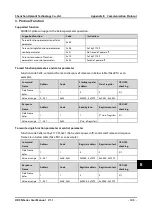
4.
Address Mapping
The function parameters and status parameters are all mapped as MODBUS’s read-write register.
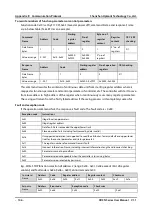
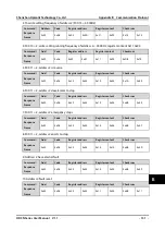
Function code address mapping
Their group numbers are mapped as higher bytes of register address while the relationships are shown
as below table. The intergroup indexes are mapped as lower bytes. Please refer to user manual for F00 -
F23, R02.
High bytes of
register address
Group
number
High bytes of
register address
Group
number
High bytes of
register address
Group
number
0x00
F00
0x07
F07
0x11
F17
0x01
F01
0x08
F08
0x12
F18
0x02
F02
0x09
F09
0x13
F19
0x03
F03
0x0a
F10
0x14
F20
0x04
F04
0x0b
F11
0x14
F21
0x05
F05
0x0f
F15
0x17
F23
0x06
F06
0x10
F16
0x1B
R02
For instance: The register address of function parameter F03.02 is 0x0302, and that of function
parameter F16.01 is 0x1001.
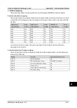
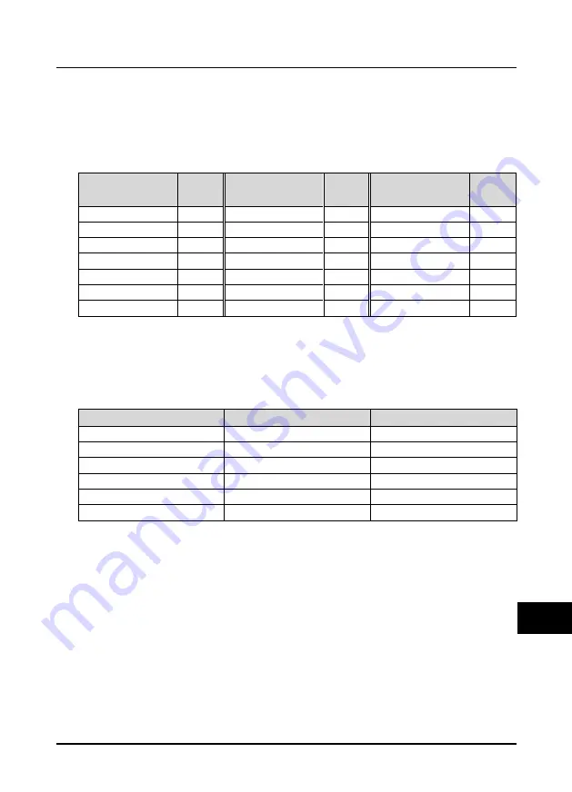
Control parameter (0x33) address mapping
The status parameters (0x33) are mapped as higher bytes of the register address, and the intergroup
indexes are as following:
Address
Function
Save at power failure or not
0x3200
Control command
No
0x3201
Running frequency setting
Set by F00.14 hundreds
0x3202
Aux running frequency setting
No
0x3203
Torque setting
No
0x3204
Virtual terminal control setting
No
0x3210
AO output setting
No
B


