background image

V1.2      2018.11

HD3Z Series

Mining Inverter

User Manual

HD3Z Series

     Mining Inverter

Summary of Contents for HD3Z Series

Page 1: ...V1 2 2018 11 HD3Z Series Mining Inverter User Manual HD3Z Series Mining Inverter...

Page 2: ...his product until you have fully understood safety precautions Note Preserve this Manual for future use If you need the User Manual due to damage loss or other reasons please contact the regional dist...

Page 3: ......

Page 4: ...Version and Revision Records Time 2018 11 Version V1 2 Revised chapter Revised contents V1 2 published...

Page 5: ......

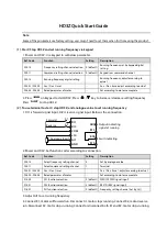
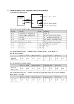
Page 6: ...ue value to set running frequency 1 DI1 is forward signal input DI2 is reverse signal input Below is the connection 2 Power on HD3Z Set function codes according to connection Ref Code Function Setting...

Page 7: ...02 Local address 2 default 3 SCI code 0x06 reads to register 0x3200 to start stop inverter which local address 2 E g Set FWD command Address Code Register address Register content Checksum Command Res...

Page 8: ...D01 01 Present MM DD Present MM DD by system D01 02 Present time Present time by system P00 00 Year Set year according to actual P00 01 MM DD Set MM DD according to actual P00 02 Time Set Hr Min acco...

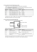
Page 9: ...nd control motor according tofrequency sequence in above table Disconnect K2 or K2 motor stops running 6 To use terminal to manually dehumidify motor 1 Below is the connection DI4 is manually dehumidi...

Page 10: ...current of motor rises F19 44 Auto dehumidifying selection 0 default According to humidity F19 45 Motor auto dehumidifying humidity 80 default Motor auto dehumidifying humidity F19 46 Motor auto dehu...

Page 11: ......

Page 12: ...ck 10 Chapter 4 Electrical Installation 11 4 1 Precautions 11 4 2 Peripheral Accessories Selection 11 4 2 1 Wiring Specifications of Input and Output 11 4 2 2 Power Terminal Lug 12 4 3 Main Circuit 12...

Page 13: ...6 Multi speed 39 6 2 8 F08 Asyn Motor Parameters 40 6 2 9 F09 V f Control Parameters 41 6 2 10 F10 Senior Parameter 1 42 6 2 11 F11 Senior Parameter 2 42 6 2 12 F15 Digital I O Terminal Parameters 43...

Page 14: ...ters 2 Product Information 3 Machenical Installation Electrical Installation 5 Operation Instructions 6 Function Introduction 7 Troubleshooting and Maintenance A MODBUS 1 Safety Information and Precau...

Page 15: ......

Page 16: ...arning contains information which is essential for avoiding a risk of damage to products or other equipements Note A Note contains information which helps to ensure correct operation of the product Pr...

Page 17: ......

Page 18: ...3Z 4T055 55 72 113 110 Frame A HD3Z 4T075 75 100 156 152 Frame A HD3Z 4T090 90 116 180 176 Frame A HD3Z 4T110 110 138 214 210 Frame B HD3Z 4T132 132 167 256 253 Frame B HD3Z 4T160 160 200 307 304 Fram...

Page 19: ...module Timing start stop function Can set 4 sets of timing start stop Timing frequency switch function Can set 8 timing frequency switch Communication protocol MODBUS protocol Protection Functions Au...

Page 20: ...conducting pollution caused by dust and condensation Humidity Less than 95 RH non condensing Oscillation 2 3 5m s2 when 2 9Hz 10m s2 when 9 200Hz IEC60721 3 3 Protection class IP54 Pollution degree De...

Page 21: ...chnology Co Ltd 6 HD3Z Series User Manual V1 2 2 5 Parts of Inverter PE U V W M OT OR L1 L2 L3 POWER Ring Keypad Front upper door Front lower door Upper door lock Connection rear Connection bottom Low...

Page 22: ...le things Do not do wiring operation until power supply is cut off for more than 10 minutes the internal charge indicator of HD3Z is off Do not let wires screws or residues fall into HD3Z when install...

Page 23: ...o keep ambient temperature between 10 40 C Install on solid material where osilation meets requirement 3 5m s2 when 2 9Hz 10m s2 when 9 200Hz IEC60721 3 3 Install at where the humidity is less than 95...

Page 24: ...s and mounting size of HD3Z are shown in Table 3 2 For the corresponding model of the mounting size refer to section 2 2 Rated Value page 3 Table 3 2 HD3Z Mounting Size Size Dimension mm Mounting size...

Page 25: ...kwise 90 and door will open step 2 Close Rotate handknob 90 anticlockwise to initial position press it vertically to lock the door Lower door lock Open Pull the handknob vertically step 3 rotate handk...

Page 26: ...circuiting Do not do dielectric strength test on HD3Z For HD3Z with more than 2 year s storage please use regulator to power it slowly Do wiring connection of the braking resistor or the braking unit...

Page 27: ...20 600 600 120 2 1 120 2 1 120 Frame C HD3Z 4T250 800 600 120 2 1 120 2 1 120 Frame C 1 2 indicates that two power lines or motor lines are connected in parallel 4 2 2 Power Terminal Lug Select the lu...

Page 28: ...k or bottom of control panel refer to section 2 5 Parts of Inverter page 6 Refer to section 4 2 Peripheral Accessories Selection page 11 for contactor supply cable motor cable and ground cable Refer t...

Page 29: ...GND Analogue supply Analogue input use 10V power supply max output current is 100mA AI1 AI2 Analogue input AI1 input voltage 0 10V input impedance 32k AI2 input current 0 20mA input impedance 500 AO1...

Page 30: ...d the motor cable The control cable must be shielded cable The analogue signal cable must be shielded twisted pair Figure 4 4 HD3Z control board conection Digital input DI connection Dry contact Refer...

Page 31: ...input signal should add filter capacitor and ferrite core as shown in Figure 4 7 AI2 is current input and range is 0 20mA refer to Figure 4 8 Figure 4 8 AI2 connection Digital Output DO Connection DO...

Page 32: ...grounding resistance should be less than 10 Do not share the grounding wire with other devices A HD3Z can share grounding pole with other devices C It achieves the best effect if HD3Z and other device...

Page 33: ...nger than 100 meters it is recommended to install AC output reactor and adjust the carrier frequency according to carrier frequency F23 00 Cable length 30m 30 50m 50 100m 100m Carrier frequency Below...

Page 34: ...times Please read this section It will help you to correctly understand and use the functions to be discussed 5 1 1 Operation Mode F00 11 and DI terminal can select command of HD3Z start running stop...

Page 35: ...mand No 20 25 function HD3Z runs according to relative frequency set F00 15 F03 15 F03 16 and F05 21 PID adjustment running PID adjustment function is valid F04 00 1 HD3Z runs in PID mode Process PID...

Page 36: ...pressing Figure 5 1 Display status parameter Function parameter editing status At stop run or fault alarm status press to enter function parameter edit status see F01 00 and section 5 2 3 Keypad Opera...

Page 37: ...ording to d F P Modify No function Increase by 1 when press this key one time Modify the internal No of function group Increase by 1 according to the present modified bit Modify function value Increas...

Page 38: ...an example Figure 5 6 shows the switching process at stop status Figure 5 6 Switching display parameters at stop status 0 5 0 0 0 Hz F00 06 Max output frequency ALM STOP FWD LO RE Fourth level menu F0...

Page 39: ...2 it uploads parameter to keypad When finished keypad displays F01 00 Download When F01 02 2 3 5 6 it downloads parameter from keypad When finished keypad displays F01 03 The upload and download param...

Page 40: ...ge 0 Invalid 1 Valid Hundred Bit11 Dehumidifing status of motor 0 Not started 1 Under way Bit10 Speed limitation 0 Below limitation 1 Above limitation Bit9 Unused Bit8 Unused Ten Bit7 DC brake 0 Inval...

Page 41: ...e Display PID tolerance relative to full scale percentage d00 47 PID integral item Actual value Display PID integral item tolerance relative to percentage of max output frequency d00 48 PID output Act...

Page 42: ...age 6 1 2 d01 Timing Display Parameter Ref Code Function Description Setting Range Default d01 00 Present year Actual value d01 01 Present MM DD Actual value d01 02 Present Min Sec Actual value d01 04...

Page 43: ...and the running frequency of HD3Z 4 DI pulse Refer to group F05 for the corresponding relationship between the pulse terminal frequency and the running frequency of HD3Z 6 AI1 7 AI2 F00 11 Command se...

Page 44: ...equency setting channel swicthes from keypad terminal digital setting keypad setting on keypad do not change F00 15 Jog running frequency digital setting 1 0 00 Upper limit frequency 5 00Hz F00 16 Int...

Page 45: ...D3Z enters dormancy status displays on keypad and stop running F00 26 Action selection of HD3Z at zero speed 00 12 11 Unit Action selection of zero speed under V f control 0 Do not process 1 HD3Z does...

Page 46: ...initialization download 0 6 0 0 No operation HD3Z is in regular parameter read write status Whether can change the parameter depends on user password status and the actual running condition of HD3Z 1...

Page 47: ...time 1 0 6000 5s F02 04 is percentage to rated current of HD3Z It sets current value of starting DC brake and stop DC brake If setting DC brake current is 5 times higher than rated current of motor t...

Page 48: ...uring stop process HD3Z does not output during waiting time of stop brake F02 17 can avoid overshoot at point B start time of brake of high power motor F02 04 sets the current at DC brake F02 18 0 the...

Page 49: ...that HD3Z decelerates from reference frequency to 0Hz in linear form Reference frequency is set by tens of F03 00 It supports Acc time or Dec time only refer to figure in F03 00 Switching of Acc Dec...

Page 50: ...00 Process PID control selection 0 1 0 0 PID control is disabled 1 PID control is enabled Note Set F04 00 0 when using aux PID F04 01 Setting channel selection 0 4 0 0 Digital Set by F04 03 1 Analogue...

Page 51: ...en PID serves as aux frequency setting channel F04 12 is invalid the lower limit REV frequency upper limit F04 12 is valid only when PID F04 00 1 and prohibit reverse F04 18 0 0 Set by F04 14 1 Analog...

Page 52: ...ncy switching point 1 F04 24 Select group 2 when PID output frequency switching point 2 F04 25 Select linear interpolation when PID output frequency is within switching point 1 and 2 F04 24 PID parame...

Page 53: ...tion point 2 corresponding value 0 0 100 0 100 0 F05 13 Inflection point 1 setting of polyline F05 15 F05 11 0 0 F05 14 Inflection point 1 corresponding value 0 0 100 0 0 0 F05 15 Min setting of polyl...

Page 54: ...rocess PID F05 21 Digital setting 2 of jog run frequency 0 00 Upper limit frequency 5 00Hz When terminal selects jog run 2 HD3Z runs according to F05 21 6 2 7 F06 Multi speed Ref Code Function Descrip...

Page 55: ...nt of motor 0 1 999 9A Depend on model F08 03 Rated frequency of motor 1 0 400 0 50 0Hz F08 04 Rated Rpm of motor 1 24000rpm Depend on model F08 00 F08 04 Set rated value of motor according to motor n...

Page 56: ...load According to actual condition set proper curve to meet requirements of load characteristics F09 07 Torque boost of motor 0 0 30 0 Depend on model F09 08 Cut off point used for manual torque boos...

Page 57: ...ergy saving control selection 0 3 0 0 Invalid 3 Enabled according to output current When F09 17 3 and V f control mode F00 01 0 When output frequency F09 19 and output current F09 20 rated current of...

Page 58: ...FWD REV FWD REV is valid only in terminal control mode Refer to F15 16 4 Three wire running mode Refer to F15 16 5 7 87 Frequency setting channel selection 1 4 Achieve 2n frequency setting channel vi...

Page 59: ...4 terminal function HD3Z can switch between frequency setting channel and any one of multi frequency Set 3 terminal function HD3Z can switch between frequency setting channel and 7 frequency Set 2 ter...

Page 60: ...F00 15 Jog running frequency F00 16 Jog interval F03 15 Jog Acc time and F03 16 Jog Dec time Jog direction input No 25 Jog command input No 24 Running command 0 0 Invalid 1 0 Invalid 0 1 Jog 1 FWD 1...

Page 61: ...In running when HD3Z receives external stop signal it stops output When external stop signal is cancelled and HD3Z can run it tracks and start running 41 42 Coast to stop NO NC input After HD3Z receiv...

Page 62: ...1 Negative logic Connected to corresponding common port This logic is disabled Otherwise enabled Bit7 Bit6 Bit5 Bit4 Bit3 Bit2 Bit1 Bit0 DI6 DI5 DI4 DI3 DI2 DI1 F15 16 FWD REV running mode 0 3 0 FWD D...

Page 63: ...29 7 Zero frequency running HD3Z output frequency is within zero frequency range Refer to F15 28 and F15 29 9 10 Frequency level detection signal FDT1 FDT2 Refer to F15 31 F15 35 11 Frequency within F...

Page 64: ...40 In timing start and stop process 41 In timing frequency switch process F15 24 Terminal output logic setting 000 0xFFF 00 Defines that each bit binary represents different physical channels 0 Positi...

Page 65: ...uency F15 34 FDT2 level 0 00 Upper limit frequency 50 00Hz F15 35 FDT2 delay 0 00 Upper limit frequency 1 00Hz Refer to F15 31 and F15 32 F15 39 Action selection when motor is overheated 00 30 00 If c...

Page 66: ...ut voltage 7 Process PID regulating lower limit F04 12 1 analogue sets lower limit of PID regulator process PID regulating lower limit is set by corresponding input voltage 20 Detect ambient humidity...

Page 67: ...Output power 0 twice rated power of motor 14 AI1 input 0 max AI1 after calculating 15 AI2 input 0 max AI2 after calculating 18 19 Output frequency setting frequency 1 1 times max output frequency 20 S...

Page 68: ...will not detect the communication error F17 06 Action selection at communication timeout 0 3 3 F17 07 Action selection at communication error 0 3 3 F17 08 Action selection at communication peripheral...

Page 69: ...status F18 08 F18 13 It can be cycling displayed by on keypad 0 Unused 1 Rated current of HD3Z 3 Invertre status Refer to d00 10 4 Main setting frequency channel 5 Main setting frequency 6 Aux settin...

Page 70: ...itching 123 DI 54 F19 01 setting value 00 10 20 30 40 01 11 21 31 41 0 Main Main Aux Aux Main Aux Main Aux Main Main Aux Aux Main Aux Main Aux 1 Main Main Aux Main Main Aux Main Main Aux Main Main Aux...

Page 71: ...urs when HD3Z is running DC busbar voltage of main circuit VDC F19 15 HD3Z runs non stop by decreasing output frequency and maintain DC busbar voltage 0 Forbid non stop at instantaneous power loss 1 E...

Page 72: ...VDC F19 19 F19 20 Auto current limit gain 0 000 1 000 0 500 Output frequency of HD3Z F19 21 HD3Z will limit current to avoid over current protection Adjust F19 20 according to actual load If F19 20 is...

Page 73: ...umidifying current 1 80 10 F19 43 Dehumidifying time when current of motor rises 0 1 240 0 30 0min F19 44 Motor auto dehumidification selection 0x00 0x11 0x11 Ten The basis of judgement for starting t...

Page 74: ...ffected by the motor speed due to its forced cooling potential HD3Z will not automatically make regulation to the time of motor overload protection Ten Thousand Overload protection 0 Enable inverter o...

Page 75: ...Z will not detect PID feedback out of limit fault F20 18 Fault auto reset times 0 100 0 F20 19 Fault auto reset interval 0 01 200 00 5 00s time When F20 18 0 it means auto reset is unused and the prot...

Page 76: ...rrier frequency the lower the noise made by the motor So properly set the carrier frequency When the value factory setting HD3Z should be derated by 5 when per 1kHz is increased compared to the factor...

Page 77: ...timing frequency switch 0 00 Upper limit frequency 0 00Hz P01 12 Time 2 of timing frequency switch 00 00 23 59 00 00 P01 13 Value 2 of timing frequency switch 0 00 Upper limit frequency 0 00Hz P01 14...

Page 78: ...of hardware It is normal status of power on and power off Check input power voltage Check wiring and wire HD3Z properly E0001 Inverter output overcurrent in Acc process Improper connection between inv...

Page 79: ...ut HD3Z input phase loss fault occurs to power input Check the three phase power input Seek technical support E0016 Output voltage phase loss Output voltage phase disconnection or loss Three phase loa...

Page 80: ...gue input circuit fault Check the connection Seek technical support E0026 PID feedback loss Analogue setting F20 14 Analogue input circuit fault Check the connection Seek technical support E0027 PID f...

Page 81: ...minutes For HD3Z with more than 2 years storage please use voltage regulator to increase the input voltage gradually Do not leave metal parts like screws or pads inside HD3Z Do not make modification...

Page 82: ...ng AC power to HD3Z use a voltage regulator to gradually raise the input voltage to rated input voltage at least 5 hours Replacing Damaged Parts The components that are easily damaged are Cooling fan...

Page 83: ......

Page 84: ...arity RTU Baut rate 9600bps Relative setting Refer to F17 page 53 Network Mode Protocol Format MODBUS supports RTU mode with corresponding frame format as shown below MODBUS adopts Big Endian encoding...

Page 85: ...e AI2 input voltage after calculating process PID setting process PID feedback process PID tolerance process PID integral and process PID output correspond to 1000 1000 3 Protocol Function Supported F...

Page 86: ...ved at power off Command frame and response frame are in below table take RTU as an example Command frame Address Code Starting register address No of register Byte no of register content Register con...

Page 87: ...a is exceeded the upper lower limit 0x20 Parameters cannot be modified 0x04 Slave operation fails including fault caused by data invalid 0x21 Parameters are unchangeable when the controller is in runn...

Page 88: ...parameters are used to start stop inveter set running frequency check running frequency and output current of inverter and others by searching them The status parameters 0x33 are mapped as higher byt...

Page 89: ...cy to stop 0x1080 Emergency to stop 0x1010 Coast to stop 0x1100 Coast to stop 0x1020 Stop at external fault Stop at external fault Virtual terminal control setting 0x3204 and its setting Control Bit M...

Page 90: ...0 Process PID output 0x330D Aux setting frequency 0x3332 Input terminal status 0x330E Setting frequency 0x3333 Output terminal status 0x330F Setting frequency after calculated 0x3334 MODBUS status 0x3...

Page 91: ...password When verified host computer access modifying function parameter of inverter After modifying write invalid password into F01 00 to disable this access 4 If many multi function input terminals...

Page 92: ...rame 0x02 0x03 0x33 0x19 0x00 0x01 0x5A 0xBA Address Code Answer byte Register content Checksum Response frame 0x02 0x03 0x02 0x02 0x19 0x3C 0xEE 3 To write setting frequency of address 2 F00 13 45 00...

Page 93: ...ister content Checksum Command Response frame 0x02 0x06 0x32 0x00 0x10 0x10 0x8B 0x4D 9 Address 2 has external fault Add Code Register address Register content Checksum Command Response frame 0x02 0x0...

Page 94: ...n of HD3Z 00 00 99 99 d00 05 Software version of keypad 00 00 99 99 d00 06 Customized serial number 0 9999 d00 08 Rated current of HD3Z 0 1A d00 10 Inverter status Bit0 Inverter fault Bit1 Run Stop Bi...

Page 95: ...100 0 100 0 d00 46 PID tolerance 100 0 100 0 d00 47 PID integral item 100 0 100 0 d00 48 PID output 100 0 100 0 d00 50 Input terminal status Bit0 Bit5 correspond to DI1 DI6 0 Input terminals disconnec...

Page 96: ...ation time year 0 99 d01 09 System calibration time MM DD 1 01 12 31 F00 Basic Parameters on pages 28 31 F00 06 Max output frequency of HD3Z 50 00 400 00Hz 50 00Hz 0 01Hz F00 08 Upper limit of running...

Page 97: ...s F00 17 Running direction 0 The same as running command 1 Opposite to running command 0 1 F00 18 Reverse 0 Permitted 1 Prohibitted 0 1 F00 19 Dead time of direction switch 0 0 3600 0s 0 0s 0 1s F00 2...

Page 98: ...the keypad EEPROM parameter 1 2 to the current function code settings 4 Clear fault information 5 6 Copy the keypad EEPROM parameter 1 2 to the current function code settings including the motor para...

Page 99: ...s 0 50s 0 01s F02 19 Jog control mode Unit 0 Can not jog the start and stop function 1 Can jog the start and stop function Ten 0 Terminal jog is not preferred 1 Terminal jog is preferred 10 1 F02 21 D...

Page 100: ...n pages 35 38 F04 00 Process PID control selection 0 PID control is disabled 1 PID control is enabled 0 1 F04 01 Setting channel selection 0 Digital 1 Analogue 2 Terminal pulse 3 AI1 4 AI2 0 1 F04 02...

Page 101: ...0 Do not adjust 1 DI 2 Bias 3 Frequency 0 1 F04 24 PID parameter switching point 1 0 0 F04 25 0 0 0 1 F04 25 PID parameter switching point 2 F04 24 100 0 100 0 0 1 F04 29 PID calculating mode 0 Do not...

Page 102: ...5 16 Min setting corresponding value of polyline 0 0 100 0 0 0 0 1 F05 17 Skip frequency 1 F00 09 Upper limit frequency 0 00Hz 0 01Hz F05 18 Skip frequency 2 F00 09 Upper limit frequency 0 00Hz 0 01Hz...

Page 103: ...kW Depend on model 0 1kW F08 01 Rated voltage of motor 0 999V 1V F08 02 Rated current of motor 0 1 999 9A 0 1A F08 03 Rated frequency of motor 1 0 400 0Hz 50 0Hz 0 1Hz F08 04 Rated Rpm of motor 1 2400...

Page 104: ...ing control selection 0 Invalid 3 Enabled according to output current 0 1 F09 18 Motor energy saving coefficient 0 0 100 0 5 0 0 1 F09 19 Starting frequency of motor energy saving 0 00 50 00Hz 25 00Hz...

Page 105: ...38 Stop DC brake input 39 External stop NO contact input 40 External stop NC contact input 41 42 Coast to stop NO NC input 43 Emergency stop 44 45 NO NC input for external fault 46 External reset RST...

Page 106: ...Frequency upper limit 13 Frequency lower limit 20 Signal output from SCI 22 Timing function 27 Analogue input exceeding limit 29 Stop in under voltage condition 30 Overload detection signa 31 Inverte...

Page 107: ...overheat input 0 0 100 0 100 0 0 1 F15 42 Detection time of motor overheat 0 00 50 00s 5 00s 0 01s F15 43 Terminal output delay 0 0 100 0s 0 0s 0 1s F15 45 RLY5 relay function 0 41 Function of F15 45...

Page 108: ...put power 0 twice rated power of motor 14 AI1 input 0 max AI1 after calculating 15 AI2 input 0 max AI2 after calculating 18 Output frequency 1 1 times max output frequency 19 Setting frequency 1 1 tim...

Page 109: ...0 13 and F19 03 Ten F00 13 and F19 03 storage selection 0 Do not store to EEPROM 1 Store to EEPROM F17 09 is used to select parameter storage during modifying 01 1 F17 10 Detection time of networking...

Page 110: ...r humidity 47 Motor temperature 48 Total time at power on hour 49 Total running time hour 7 1 F18 09 Set parameter 2 of stop status 18 1 F18 10 Set parameter 3 of stop status 35 1 F18 11 Set parameter...

Page 111: ...ns all the time when power on 0 1 F19 08 Fan control delay time 0 0 600 0s 120 0s 0 1s F19 10 Zero frequency threshold 0 00Hz Upper limit frequency 1 00Hz 0 01Hz F19 11 Action selection when setting f...

Page 112: ...cy calculating range 0 0 max frequency 1 Negative max frequency max frequency Hundred Resultant frequency calculating range 0 0 upper limit frequency 1 Negative upper limit frequency upper limit frequ...

Page 113: ...F20 00 Overload pre alarm detection Unit Overload pre alarm detection 0 It is active all the time in running status 1 It is active only at constant speed Ten Overload pre alarm action 0 HD3Z doesn t...

Page 114: ...Not detect PID setting loss fault 0 20s 0 01s F20 14 PID feedback loss detection value 0 100 0 Not detect PID feedback loss fault 0 1 F20 15 PID feedback loss detection time 0 00 10 00s 0 00 Not detec...

Page 115: ...run of controller E0023 Faulty setting of parameters E0024 Fault of external equipment E0025 PID setting loss E0026 PID feedback loss E0027 PID feedback out of limit E0028 SCI communication timeout E...

Page 116: ...d on model 0 01Hz F23 05 Switch point 2 of PWM modulation mode 0 00 50 00Hz Depend on model 0 01Hz F23 09 Random carrier factor K1 0 2000 2 1 F23 10 Random carrier factor K2 0 2000 3 1 P00 Timing Time...

Page 117: ...1 16 Time 4 of timing frequency switch 00 00 23 59 00 00 0 01 P01 17 Value 4 of timing frequency switch 0 00Hz Upper limit frequency 0 00Hz 0 0 P01 18 Time 5 of timing frequency switch 00 00 23 59 00...

Reviews: