


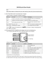


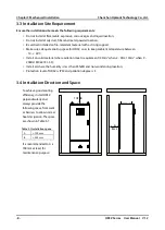
(4). To use terminal to control timing start / stop HD3Z
1. Check that HD3Z is installed properly. DI1: Forward signal input; DI2: Reverse signal input. Below is
the connection.
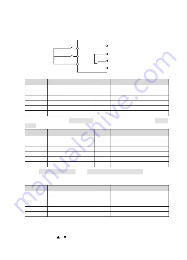
2. Power on, and set function parameters as per below table:
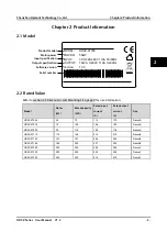
Ref. Code
Function
Setting
Meaning
F00.10
To select frequency setting channel
0 (default) Set by keypad digital setting
F00.11
To select command setting channel
1
Running command set by terminal
F00.13
Running frequency digital setting
-
Running frequency, set according to actual
F03.01 / F03.02
Acc. / Dec. time 1
-
Acc. / Dec. time, adjust according to actual
F15.00
DI1 function selection
2 (default) FWD (DI FWD signal input)
F15.01
DI2 function selection
3 (default) REV (DI REV signal input)
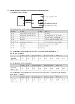
3. Check present time and date (D01.00 - D01.02). If not synchronize with real time, reset time (P00.00 -
P00.02).
Ref. Code
Function
Setting
Meaning
D01.00
Present year
-
Present year by system
D01.01
Present MM/DD
-
Present MM/DD by system
D01.02
Present time
-
Present time by system
P00.00
Year
-
Set year (according to actual)
P00.01
MM/DD
-
Set MM/DD (according to actual)
P00.02
Time
-
Set Hr/Min (according to actual)
4. Enable timing start / stop (P01.00) and set timing start / stop time (P01.01 - P01.08) according to
actual needs. For instance: Set inverter start at 8:00, stop at 12:00, start at 14:00, stop at 17:30.
Refer to below:
Ref. Code
Function
Setting
Meaning
P01.00
Timing start and stop selection
1
Valid, enable timing start and stop
P01.01
Timing start 1
8.00
Start
P01.02
Timing stop 1
12.00
Stop
P01.03
Timing start 2
14.00
Start
P01.04
Timing stop 2
17.30
Stop
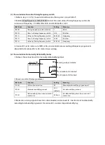
5. Connect K1 or K2 to enable timing start or stop function. Inverter will auto controls motor to run
FWD or REV or stop according to time sequence in above table. Disconnect K1 or K2, motor stops
running, inverter exits timing start / stop function.
6. Set F00.13 or press
/ on keypad to increase / decrease setting frequency.
DI1
COM
K1
K2
DI2
DO1
R1C
R1B
R1A
Forward
Output indicating
signal at running
Fault indicating
Reverse


