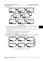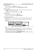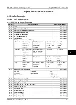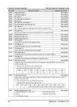
Chapter 4 Electrical Installation
Shenzhen Hpmont Technology Co., Ltd.
-12-
HD3Z Series User Manual V1.2
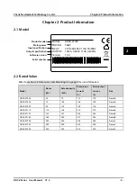
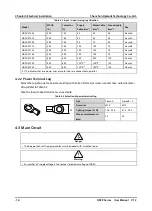
Table 4-2 Input / Ouput wiring specification
Model
MCCB
(A)
Contactor
(A)
Supply
Cable (mm
2
)
Motor Cable
(mm
2
)
Ground cable
(mm
2
)
Size
HD3Z-4T055
200
125
50
50
25
Frame A
HD3Z-4T075
250
160
50
50
25
Frame A
HD3Z-4T090
250
160
95
70
50
Frame A
HD3Z-4T110
350
350
120
120
70
Frame B
HD3Z-4T132
400
400
120
120
70
Frame B
HD3Z-4T160
500
400
185
185
95
Frame B
HD3Z-4T200
600
600
240
240
120
Frame C
HD3Z-4T220
600
600
120*2
(1)
120*2
(1)
120
Frame C
HD3Z-4T250
800
600
120*2
(1)
120*2
(1)
120
Frame C
(1): *2 indicates that two power lines or motor lines are connected in parallel.
4.2.2
Power Terminal Lug
Select the lug of power terminal according to the size of terminal, screw size and max. outer diameter
of lug. Refer to Table 4-3.
Take the round naked terminal as an example.
Table 4-3 Selection of power terminal lug
Size
Frame A
Frame B / C
Screw size
M10
M12
Tighting torque (N. M)
17.6 - 22.5
31.4 - 39.2
Max. outer diameter d
(mm)
30
35
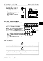
4.3
Main Circuit
•
The bare portions of the power cables must be bound with insulation tapes.
•
Ensure that AC supply voltage is the same as rated input voltage of HD3Z.
d
Danger
Warning

