background image

VDLPROM1_v2


VELLEMAN 

3.  General Guidelines 


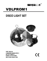
This set includes a mirror ball and pin spot for use at home, on stages, in discotheques, in theatres etc. 


The 

VDLPROM1

 should only be used indoors with an alternating current of 230V AC/50Hz. 


Lighting effects are not designed for permanent operation: regular operation breaks will prolong their lives. 


Do not shake the device. Avoid brute force when installing or operating the device. 


Select a location where the device is protected against extreme heat (see “

7. Technical Specifications

”), dust and 

moisture. Respect a minimum distance of 0.5m between the device’s light output and any illuminated surface. 


Use an appropriate safety cable to fix the device (e.g. 

VDLSC7

 or 

VDLSC8

). 


Familiarise yourself with the functions of the device before actually using it. Do not allow operation by unqualified 
people. Any damage that may occur will most probably be due to unprofessional use of the device. 


Use the original packaging if the device is to be transported. 


All modifications of the device are forbidden for safety reasons. 


Only use the device for its intended purpose. All other uses may lead to short circuits, burns, electroshocks, lamp 
explosion, crash, etc. Using the device in an unauthorised way will void the warranty. 


4.  Installation 


a)  Lamps


Only fit or replace a lamp when the device is unplugged from the mains. 


Only operate the device with a fastened lamp. 


Let a lamp cool down before replacing it as the temperature of a lamp can reach 150°C during operation. 


Do not install lamps with a higher wattage. They get hotter than this device was designed for. 


Replace any deformed or damaged lamp with a lamp of the same type (see “

7. Technical Specifications

”): 

1.  Unscrew the front ring, holding the lamp into place. 
2.  Remove the old lamp and unscrew the wires from it. 
3.  Fasten the wires to the new lamp, put it in the housing and fix it by fastening the fixation ring. 


b)  Colour Wheel


1.  Carefully unpack the colour wheel and remove the protective film. 
2.  Fix the colour wheel to the axe of the motor by means of the screw provided. 
 

c)  The Pin Spot


Have the device installed by a qualified person, respecting EN 60598-2-17 and all other applicable norms. 


The construction to which the pin spot is attached should be able to support 10 times the weight of the device for 
one hour without deformation. 


The installation must always be secured with a secondary attachment e.g. a safety cable. 


Never stand directly below the device when it is being mounted, removed or serviced. Have a qualified technician 
check the device once a year and once before you bring it into service. 


Install the device in a location with few passers-by that is inaccessible to unauthorised persons. 


Overhead mounting requires extensive experience: calculating work load limits, determining the installation 
material to be used… Have the material and the device itself checked regularly. Do not attempt to install the 
device yourself if you lack these qualifications as improper installation may result in injuries. 


Adjust the desired inclination angle via the mounting bracket and tighten the bracket screws. 


Make sure there is no flammable material within a 50cm radius of the device. 


Have a qualified electrician carry out the electric connection. 


Connect the device to the mains with the power plug. Don’t connect it to a dimming pack. 


The installation has to be approved by an expert before the device is taken into service. 


Summary of Contents for VDLPROM1

Page 1: ...VDLPROM1 DISCO LIGHT SET USER MANUAL GEBRUIKERSHANDLEIDING NOTICE D EMPLOI MANUAL DEL USUARIO BEDIENUNGSANLEITUNG...

Page 2: ...VDLPROM1_v2 VELLEMAN 2...

Page 3: ...guidelines in this manual is not covered by the warranty and the dealer will not accept responsibility for any ensuing defects or problems A qualified technician should install and service this devic...

Page 4: ...rmed or damaged lamp with a lamp of the same type see 7 Technical Specifications 1 Unscrew the front ring holding the lamp into place 2 Remove the old lamp and unscrew the wires from it 3 Fasten the w...

Page 5: ...re the device is taken into service 5 Use After connecting the devices to the mains the mirror ball motor will rotate at 3 RPM the lamp will be on and the colour wheel will be turning By aiming the sp...

Page 6: ...tselijke autoriteiten inzake verwijdering Dank u voor uw aankoop Lees deze handleiding grondig voor u het toestel in gebruik neemt Ga na of het toestel niet werd beschadigd tijdens het transport Zo ja...

Page 7: ...reen Vermijd brute kracht tijdens de installatie en de bediening van dit toestel Installeer het toestel weg van extreme temperaturen zie 7 Technische specificaties vochtigheid en stof Zorg voor een mi...

Page 8: ...lleer dit toestel op een plaats waar niemand langs moet lopen kan neerzitten of het toestel kan aanraken Een degelijke praktijkervaring is vereist voor de plaatsing van dit toestel U moet de maximumbe...

Page 9: ...vironnementales importantes concernant ce produit Ce symbole sur l appareil ou l emballage indique que l limination d un appareil en fin de vie peut polluer l environnement Ne pas liminer un appareil...

Page 10: ...aduellement Ne regardez pas directement la source lumineuse comme ceci peut entra ner des crises d pilepsie chez certains gens Remplacez tout cran objectif ou filtre UV endommag p ex fissures ou rayur...

Page 11: ...hnicien qualifi doit v rifier la construction portante et l appareil m me N essayez pas d installer cet appareil vous m me si vous n avez pas les qualifications requises une installation incorrecte pe...

Page 12: ...a pas de parties maintenables par l utilisateur part la lampe et le disque color voir 4 Installation 8 Commandez des pi ces de rechange ventuelles chez votre revendeur 9 V rifiez souvent si la bague...

Page 13: ...de alimentaci n de la red antes de abrir la caja Da os causados por descuido de las instrucciones de seguridad de este manual invalidar n su garant a y su distribuidor no ser responsable de ning n da...

Page 14: ...se l mparas con m s vatios porque stas generan temperaturas para las que este aparato no ha sido dise ado Reemplace cada l mpara deformada o defectuosa por una l mpara del mismo tipo v ase 7 Especific...

Page 15: ...ectamente horizontal Se encuentran 3 agujeros en la parte inferior de la base Aseg rese de que la bola de espejos pueda girar sin obst culos y que no sea posible un impacto lateral Un experto debe pro...

Page 16: ...Produktes nach seinem Lebenszyklus der Umwelt Schaden zuf gen kann Entsorgen Sie die Einheit oder verwendeten Batterien nicht als unsortiertes Hausm ll die Einheit oder verwendeten Batterien m ssen v...

Page 17: ...al und Rauch oder Geruch werden allm hlich verschwinden Blicken Sie niemals direkt in die Lichtquelle da bei empfindlichen Menschen epileptische Anf lle ausgel st werden k nnen Tauschen Sie besch digt...

Page 18: ...Motors c Der Punktstrahler Betrachten Sie erst den Inhalt der Richtlinie EN 60598 2 17 und die eventuellen nationalen Normen ehe Sie das Ger t installieren Die Installation darf nur von einer Fachkra...

Page 19: ...ie Befestigungsschrauben Sorgen Sie daf r dass die Spiegelkugel ungehindert drehen kann und dass keine seitliche Wirkung auf das Ger t m glich ist Die Installation muss vor Inbetriebnahme von einem Ex...

Page 20: ...chmesser 20cm 8 Gesamtgewicht 0 9kg Spiegelkugelmotor Spannungsversorgung 230VAC 50Hz Verbrauch max 4W Drehgeschwindigkeit 3 U Min Abmessungen 110 x 45mm Gesamtgewicht 0 22kg Max Durchmesser der Spieg...

Reviews: