VDP150CC6_v2
HQ POWER
4
•
Use the original packaging if the device is to be transported.
•
All modifications of the device are forbidden for safety reasons.
•
Only use the device for its intended purpose. All other uses may lead to short circuits, burns, electroshocks,
crash, etc. Using the device in an unauthorized way will void the warranty.
4. Installation
a.
Fitting the lamp
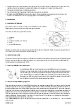
Use an Allen key and loosen the screws holding the cast aluminium housing of the
lamp hole. Loosen the 4 screws and open the cover.
After removing the cover you will see the 3 colour filters.
1.
bulb
2.
screw A
3.
six mirrors distributes over 3 layers
4.
screw B
5.
reflecting cup
Carefully move the mirrors to the two sides so as to uncover the lamp. Use a Phillips-head screwdriver and carefully
loosen the two screws in order to remove the reflector. Removing the reflector will uncover the lamp socket.
b.
Connecting the units
Connect the signal line output from the control panel to the signal line input from the first fixture. Next, connect the
output from the fixture to the input of the next fixture. Note that the DMX cable of the last fixture must be terminated
with a 120
Ω
resistance.
c.
DMX512 Chain with Termination
A DMX terminator is recommended for installations where the DMX cable has to run a
long distance or is in an electrically noisy environment (e.g. discos). The terminator
prevents corruption of the digital control signal by electrical noise. The DMX terminator is
simply an XLR plug with a 120
Ω
resistor between pins 2 and 3, which is then plugged into
the XLR output socket of the last device in the chain.
Please see illustrations.
d.
Projector DMX Start Address Selection
All DMX-controlled devices need a digital start address so that the correct device responds to the signals. This start
address is the channel number from which the device starts to “listen” to the DMX controller. Enter the correct
number and read it from the display located on the base of the
VDP150CC6
.
You can use the same starting address for a whole group of devices or enter an individual one for every device.
When all devices have the same address, all the
VDP150CC6
s will “listen” to the control signal on one particular
channel. In other words: changing the settings of one channel will affect all devices simultaneously. If you set
different addresses, each device will “listen” to a separate channel number. Changing the settings of one channel will
only affect the device in question.
In the case of the 6-channel
VDP150CC6
, you will have to set the start address of the first
VDP150CC6
to 1, the
second
VDP150CC6
to 7 (1 + 6), the third to 13 (7 + 6) and so on.
Summary of Contents for VDP150CC6
Page 2: ...VDP150CC6_v2 HQ POWER 2...


