background image

VDPL192UV


HQPOWER 


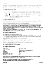
DMX512 Connection 


Connect the provided XLR cable to the female 3-pin XLR output of your controller and the other side to the male 3-

pin XLR input of the 

VDPL192UV

. Multiple 

VDPL192UV

s can be linked through serial linking. The linking cable 

should be a two-core screened cable with XLR input and output connectors. 


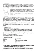
DMX512 Chain with Termination 


A DMX terminator is recommended for installations where the DMX cable has to run a 

long distance or is in an electrically noisy environment (e.g. discos). The terminator 

prevents corruption of the digital control signal by electrical noise. The DMX terminator is 

simply an XLR plug with a 120

 resistor between pins 2 and 3, which is then plugged into 

the XLR output socket of the last device in the chain. 

Please see illustrations. 


DMX Start Address Selection 


All DMX-controlled devices need a digital start address so that the correct device responds to the signals. This start 

address is the channel number from which the device starts to “listen” to the DMX controller. Enter the correct 

number and read it from the display located on the base of the 

VDPL192UV

You can use the same starting address for a whole group of devices or enter an individual one for every device. 

When all devices have the same address, all the 

VDPL192UV

s will “listen” to the control signal on one particular 

channel. In other words: changing the settings of one channel will affect all devices simultaneously. If you set 

different addresses, each device will “listen” to a separate channel number. Changing the settings of one channel will 

only affect the device in question. 

In the case of the 3-channel 

VDPL192UV

, you will have to set the start address of the first 

VDPL192UV

 to 1, the 

second 

VDPL192UV

 to 4 (1 + 3), the third to 7 (4 + 3) and so on. 


8. Cleaning and Maintenance 


1.  All screws should be tightened and free of corrosion. 

2.  The housing, visible parts, mounting supports and the installation location (e.g. ceiling, suspension, trussing) 

should not be deformed, modified or tampered with e.g. do not drill extra holes in mounting supports, do not 

change the location of the connections. 

3.  Moving mechanic parts must not show any signs of wear and tear. 

4.  The electric power supply cables must not show any damage. Have a qualified technician maintain the device. 

5.  Disconnect the device from the mains prior to maintenance activities. 

6.  Wipe the device regularly with a moist, lint-free cloth. Do not use alcohol or solvents. 

7.  There are no user-serviceable parts. 

8.  Contact your dealer for spare parts if necessary. 


9. Technical Specifications 


Power Supply 

max. 230VAC / 50Hz 

Power Consumption 

25W 

Fuse 

2A, 250VAC (5 x 20mm) (order code 

FF2N

Dimensions 

388 x 247 x 88mm 

Total Weight 

3kg 

Max. Ambient Temperature 

45°C 

Max. Housing Temperature 

50°C 


Use this device with original accessories only. Velleman nv cannot be held responsible in the event of 

damage or injury resulted from (incorrect) use of this device. 


For more info concerning this product, please visit our website www.hqpower.com. 

The information in this manual is subject to change without prior notice. 

Summary of Contents for VDPL192UV

Page 1: ...ED LED UV WASH 192 LEDS DMX STURING EFFET WASH LED UV 192 LED PILOTAGE DMX EFECTO WASH CON LEDs UV 192 LEDs CONTROL DMX LED UV WASH 192 LEDs DMX GESTEUERT USER MANUAL GEBRUIKERSHANDLEIDING NOTICE D EM...

Page 2: ...VDPL192UV HQPOWER 2...

Page 3: ...age stated in the specifications of this manual Do not crimp the power cord and protect it against damage Have an authorised dealer replace it if necessary Disconnect the device from the mains to clea...

Page 4: ...experience calculating workload limits determining the installation material to be used Have the material and the device itself checked regularly Do not attempt to install the device yourself if you l...

Page 5: ...tailored to your personal needs Each DMX fixture can be controlled using a DMX controller Press MODE until D XXX is displayed Detailed DMX Values per Channel Channel Function From To Description 0 29...

Page 6: ...neously If you set different addresses each device will listen to a separate channel number Changing the settings of one channel will only affect the device in question In the case of the 3 channel VD...

Page 7: ...ning in de specificaties achteraan de handleiding De voedingskabel mag niet omgeplooid of beschadigd zijn Laat uw dealer zo nodig een nieuwe kabel plaatsen Trek de stekker uit het stopcontact trek nie...

Page 8: ...e plaatsing van dit toestel U moet de maximumbelasting van de draagconstructie kunnen berekenen weten welk constructiemateriaal u kunt gebruiken en u moet het gebruikte materiaal en het toestel af en...

Page 9: ...ogramma s naar keuze Elk DMX toestel kan via een DMX controller bediend worden Druk op MODE tot D XXX op de lcd verschijnt Gedetailleerde DMX waarden per kanaal Kanaal Functie Van Tot Omschrijving 0 2...

Page 10: ...u verschillende adressen instelt dan luistert elk toestel naar een ander kanaal Met andere woorden wanneer u de instellingen van een kanaal verandert zal enkel het toestel op dat kanaal reageren In h...

Page 11: ...d passer la tension mentionn e dans les sp cifications la fin de cette notice Le c ble d alimentation ne peut pas tre repliss ou endommag Demander votre revendeur de renouveler le c ble d alimentatio...

Page 12: ...nce pratique le calcul de la charge max de la construction les mat riaux d installation requis etc De temps en temps un technicien qualifi doit v rifier la construction portante et l appareil m me Ne...

Page 13: ...mmes personnalis s Chaque appareil DMX est contr lable depuis un contr leur DMX Enfoncer la touche MODE jusqu ce que D XXX soit affich Valeurs DMX d taill es par canal Canal Fonction De Description 0...

Page 14: ...reils seront donc influenc s lorsque vous changez les r glages d un seul canal Avec des adresses de d part individuelles chaque appareil coutera son propre canal Par cons quent un ajustement des r gla...

Page 15: ...ada en las especificaciones No aplaste el cable de alimentaci n y prot jalo contra posibles da os causados por alg n tipo de superficie afilada Si es necesario pida a su distribuidor reemplazar el cab...

Page 16: ...ga m x del soporte debe conocer los materiales necesarios para la instalaci n etc De vez en cuando una verificaci n de la estructura y del aparato mismo debe ser llevada a cabo por un t cnico especial...

Page 17: ...as personalizados Cada aparato DMX se controla con un controlador DMX Pulse la tecla MODE hasta que D XXX se visualice Valores DMX detallados por canal Canal Funci n De A Descripci n 0 29 Abierto 30 5...

Page 18: ...los ajustes de un solo canal afecta a los ajustes de todos los canales Con varias direcciones iniciales cada aparato reaccionar independientemente Por lo tanto cambiar los ajustes de un solo canal s l...

Page 19: ...ungsanleitung Achten Sie darauf dass die Netzleitung nicht gequetscht oder durch scharfe Kanten besch digt werden kann Bei Besch digungen soll eine Fachkraft das Kabel ersetzen Trennen Sie das Ger t b...

Page 20: ...der unzug nglich ist f r Unbefugte Oberirdische Montage erfordert erhebliche Sachkenntnis in Bezug auf das Berechnen der maximalen Lasten das geeignete Montagematerial Lassen Sie das Material und das...

Page 21: ...erung entwerfen Sie eigene Programme je nach Wahl Jedes DMX Ger t kann ber DMX Controller bedient werden Dr cken Sie MODE bis D XXX im LCD Display erscheint Detaillierte DMX Werte pro Kanal Kanal Funk...

Page 22: ...en aller Kan le Definieren Sie mehrere Adressen so funktionieren alle Ger te unabh ngig voneinander Mit anderen Worten wenn Sie die Einstellungen f r 1 Kanal ver ndern werden nur die Einstellungen von...

Reviews: