background image

VDPL300D


HQPOWER™ 

4

7. DMX 

Mode 


The DMX mode allows you to control the unit through a universal DMX controller. Set DIP switch 10 
to ON to activate the DMX mode, set the DMX address using DIP switches 1 to 9. 


Detailed DMX Values per Channel 


Channel Function 

From 

To 

Description 

1 ~ 6 

Clusters 

0 10 

No 

function 

11 45 

Red 

46 80 

Green 

81 115 

Blue 

116 

150 

Red – green 

151 

185 

Red – blue 

186 

220 

Green – blue 

221 255 

RGB 

7 Strobe 

0 10 

No 

function 

11 255 

S>F 

strobe 

8 Auto 

speed 

0 10 

No 

function 

11 24 

Auto 

25 38 

Auto 

39 52 

Auto 

53 66 

Auto 

67 80 

Auto 

81 94 

Auto 

95 108 

Auto 

109 122 

Auto 

123 136 

Auto 

137 150 

Auto 

10 

151 164 

Auto 

11 

165 178 

Auto 

12 

179 192 

Auto 

13 

193 206 

Auto 

14 

207 220 

Auto 

15 

221 249 

Auto 

15 

251 255 

Auto 

trigger 


DMX512 Connection 

 
Connect the provided XLR cable to the female 3-pin XLR output of your controller and the other side 

to the male 3-pin XLR input of the 

VDPL300D

. Multiple 

VDPL300D

s can be linked through serial 

linking. The linking cable should be a two-core screened cable with XLR input and output connectors. 
 

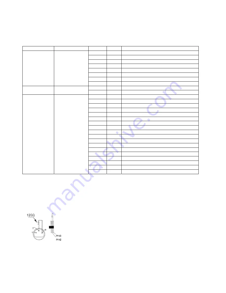
DMX512 Chain with Termination 


A DMX terminator is recommended for installations where the DMX cable has 
to run a long distance or is in an electrically noisy environment (e.g. discos). 

The terminator prevents corruption of the digital control signal by electrical 
noise. The DMX terminator is simply an XLR plug with a 120

 resistor 

between pins 2 and 3, which is then plugged into the XLR output socket of 
the last device in the chain. 
Please see illustrations. 


DMX512 Start Address 

 
All DMX-controlled devices need a digital start address so that the correct device responds to the 

signals. This start address is the channel number from which the device starts to “listen” to the DMX 
controller. Enter the correct number and read it from the display located on the base of the 

VDPL300D

Summary of Contents for VDPL300D

Page 1: ...SER M VDPL300D DP R LED F E D MANUAL H A PL3 D DERB BYEF ET DE ECTO D DERB L 300 BY DM FECT RBY DERBY BY DM 0D MX CO DMX T CON L MX GE D ONTRO U TAGE D LEDs STEUE LLED UURD DMX CONTR ERT ROL DMX VDPL300DVDPL300D ...

Page 2: ...lass I I electric co ltage does nd protect i mains to c source as ser modifica are not cov dren and u es on stage in rrent of 23 ed for perm brute force ice is prote tween the d e to fix the nctions of t Any dama e e device is e installatio m rain and fore openin 2 NGLIS bout this p ckage indica t Do not d to a specia or or to a lo posal auth PL300D is nging this d our dealer uidelines in ty for a...

Page 3: ... material to be used Have the material and the device itself checked regularly Do not attempt to install the device yourself if you lack these qualifications as improper installation may result in injuries Adjust the desired inclination angle via the mounting bracket and tighten the bracket screws Make sure there is no flammable material within a 0 5m radius of the device Have a qualified electric...

Page 4: ...tput of your controller and the other side to the male 3 pin XLR input of the VDPL300D Multiple VDPL300Ds can be linked through serial linking The linking cable should be a two core screened cable with XLR input and output connectors DMX512 Chain with Termination A DMX terminator is recommended for installations where the DMX cable has to run a long distance or is in an electrically noisy environm...

Page 5: ...The electric power supply cables must not show any damage Have a qualified technician maintain the device 5 Disconnect the device from the mains prior to maintenance activities 6 Wipe the device regularly with a moist lint free cloth Do not use alcohol or solvents 7 There are no user serviceable parts 8 Contact your dealer for spare parts if necessary 9 Technical Specifications Power Supply 230VAC...

Reviews: