background image

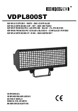
VDPL800ST


HQPOWER 


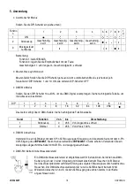
DMX512 Mode 


Set DIP switch 10 to on to receive the DMX signal; refer to the table below the set the address. 


DIP 

10 


16 

32 

64 

128 

256 


The unit has 2 DMX channels. Refer to the table below for the setting. 


Channel 

Function 

From 

To 

Description 

Strobe 

255  From slow to fast 

Dimmer 

255  From 0% to 100% output 


DMX512 Connection 


Connect the provided XLR cable to the female 3-pin XLR output of your controller and the other side to the 

male 3-pin XLR input of the 

VDPL800ST

. Multiple 

VDPL800ST

s can be linked through serial linking. The 

linking cable should be a two-core screened cable with XLR input and output connectors. 


DMX512 Chain with Termination 


A DMX terminator is recommended for installations where the DMX cable has to run a 

long distance or is in an electrically noisy environment (e.g. discos). The terminator 

prevents corruption of the digital control signal by electrical noise. The DMX terminator is 

simply an XLR plug with a 120

 resistor between pins 2 and 3, which is then plugged into 

the XLR output socket of the last device in the chain. 

Please see illustrations. 


DMX Start Address Selection 


All DMX-controlled devices need a digital start address so that the correct device responds to the signals. This 

start address is the channel number from which the device starts to “listen” to the DMX controller. Enter the 

correct number and read it from the display located on the base of the 

VDPL800ST

You can use the same starting address for a whole group of devices or enter an individual one for every 

device. 

When all devices have the same address, all the 

VDPL800ST

s will “listen” to the control signal on one 

particular channel. In other words: changing the settings of one channel will affect all devices simultaneously. 

If you set different addresses, each device will “listen” to a separate channel number. Changing the settings of 

one channel will only affect the device in question. 

In the case of the 2-channel 

VDPL800ST

, you will have to set the start address of the first 

VDPL800ST

 to 1, 

the second 

VDPL800ST

 to 3 (1 + 2), the third to 5 (3 + 2) and so on. 


6. Cleaning and Maintenance 


1.  All screws should be tightened and free of corrosion. 

2.  The housing, visible parts, mounting supports and the installation location (e.g. ceiling, suspension, trussing) 

should not be deformed, modified or tampered with e.g. do not drill extra holes in mounting supports, do not 

change the location of the connections. 

3.  Moving mechanic parts must not show any signs of wear and tear. 

4.  The electric power supply cables must not show any damage. Have a qualified technician maintain the device. 

5.  Disconnect the device from the mains prior to maintenance activities. 

6.  Wipe the device regularly with a moist, lint-free cloth. Do not use alcohol or solvents. 

7.  There are no user-serviceable parts except for the fuse. 

8.  Contact your dealer for spare parts if necessary. 

Summary of Contents for VDPL800ST

Page 1: ...TROBOSCOOP WIT DMX GESTUURD SUPER STROBOSCOPE LED STROBE BLANC PILOTAGE DMX S PER ESTROBOSCOPIO CON LEDs BLANCOS CONROLADO POR DMX SUPER LEDSTROBOSKOP WEI DMX GESTEUERT USER MANUAL GEBRUIKERSHANDLEIDI...

Page 2: ...VDPL800ST HQPOWER 2...

Page 3: ...available voltage does not exceed the voltage stated in the specifications of this manual Do not crimp the power cord and protect it against damage Have an authorised dealer replace it if necessary Di...

Page 4: ...evice in a location with few passers by that is inaccessible to unauthorised persons Overhead mounting requires extensive experience calculating workload limits determining the installation material t...

Page 5: ...o the DMX controller Enter the correct number and read it from the display located on the base of the VDPL800ST You can use the same starting address for a whole group of devices or enter an individua...

Page 6: ...en krachtige ledstroboscoop met hoogwaardige witte leds van 10mm Lees deze handleiding grondig voor u het toestel in gebruik neemt Werd het toestel beschadigd tijdens het transport installeer het dan...

Page 7: ...t eerste gebruik gekeurd worden door een expert 4 Installatie a Algemeen Het toestel kan aan de muur of aan het plafond gemonteerd worden Kies een geschikte montageplaats en regel de gewenste invalsho...

Page 8: ...l hieronder Kanaal Functie Van Tot Omschrijving 1 Stroboscoop 0 255 Van traag naar snel 2 Dimmer 0 255 Van 0 naar 100 DMX512 aansluiting Sluit de meegeleverde XLR kabel aan de vrouwelijke 3 pin XLR ui...

Page 9: ...goed zijn aangespannen en mogen geen sporen van roest vertonen 2 De behuizing de lenzen de montagebeugels en de montageplaats bvb het plafond of het gebinte mogen niet vervormd zijn of aangepast word...

Page 10: ...ctrique La tension r seau ne peut pas d passer la tension mentionn e dans les sp cifications la fin de cette notice Le c ble d alimentation ne peut pas tre repliss ou endommag Demander votre revendeur...

Page 11: ...ou du nettoyage Un technicien qualifi doit r viser l appareil avant la mise en service Organiser une r vision minutieuse annuelle Installer l appareil un endroit o personne ne peut passer ou s asseoi...

Page 12: ...bruit lectrique p ex une discoth que La r sistance de terminaison pr vient la corruption du signal de contr le num rique par le bruit lectrique La r sistance de terminaison DMX n est rien d autre qu u...

Page 13: ...ect de cet appareil Pour plus d information concernant cet article visitez notre site web www hqpower com Toutes les informations pr sent es dans cette notice peuvent tre modifi es sans notification p...

Page 14: ...nte CA de m x 230VCA 50Hz Un efecto luminoso no ha sido dise ado para un uso ininterrumpido Introduzca frecuentemente una pausa para prolongar la vida del aparato No agite el aparato Evite usar excesi...

Page 15: ...la conexi n el ctrica Conecte el aparato a la red el ctrica con la conexi n de alimentaci n Normalmente no se conectan efectos luminosos a dimmer packs reguladores Un experto debe probar la instalaci...

Page 16: ...es de un solo canal afecta a los ajustes de todos los canales Con varias direcciones iniciales cada aparato reaccionar independientemente Por lo tanto cambiar los ajustes de un solo canal s lo afecta...

Page 17: ...tisiert ist Zimmertemperatur erreicht hat Der Aufbau des Ger tes entspricht der Schutzklasse I Gem den Vorschriften muss das Ger t geerdet sein Der elektrische Anschluss darf nur von einer Fachkraft d...

Page 18: ...ie das Ger t ber den Stecker mit dem Netz Schalten Sie das Ger t aus ehe Sie den Stecker aus der Steckdose ziehen b Das Ger t montieren Lassen Sie das Ger t von einem Fachmann und gem den EN 60598 2 1...

Page 19: ...4 8 16 32 64 128 256 Das Ger t verf gt ber 2 DMX Kan le Siehe nachfolgende Funktionstabelle Kanal Funktion Von bis Umschreibung 1 Stroboskop 0 255 Von langsam bis schnell 2 Dimmer 0 255 Von 0 bis 100...

Page 20: ...d d rfen keine Rostspuren zeigen 2 Das Geh use die Linsen die Montageb gel und der Montageort z B Decke oder Gebinde d rfen nicht angepasst werden z B bohren Sie keine zus tzlichen L cher in Montageb...

Reviews: