-
12
-
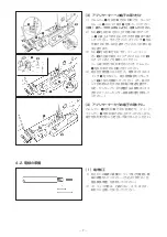
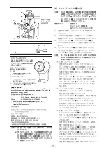
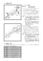
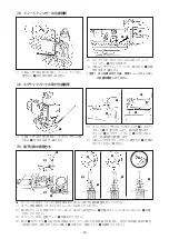
(2) 夹紧高度的调整方法
( 注意 ) 进行冲压工作时,请一定用手动操作确
认了端子压接位置之后再进行操作。此
时,线圆盘
1
、衬垫圆盘
2
、调整拨盘
3
、
调整拨盘 GT
4
的位置是 A-W-1-1。
准备物品 ・压接条件表
・夹紧高度测定器具 ( 点板测微计等 )
1) 请确认压接电线的夹紧高度条件。
2) 此端子压接部位是芯线部 C、屏蔽部 D 和被
覆部 E 共 3 处。请按照以下的顺序进行调整。
3) 请把线圆盘
1
、衬垫圆盘
2
对准 A-W。( 正
面位置是设定位置。)
4) 请把调整拨盘
3
对准 1 号。 ( 正上方的位
置是设定位置。) 向前拉调整拨盘
3
,就
可以转动。
( 注意 ) 拨盘
3
是弹簧式,手离开后,会自动
地返回,因此请一定确认是否确实地进入
档位。
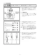
1
芯线夹紧高度的调整
・ 进行压接,用 DF1B 高度计测定芯线
夹紧高度,确认与规格值的差。
・ 参考下列数值,把线圆盘
1
、衬垫圆盘
2
的位置调整导夹紧高度条件值内。
・ 线圆盘
1
,请按照 A → B → C → D 的
顺序调整,1 档约降低夹紧高度 0.12mm。
・ 衬垫圆盘
2
,请按照 W → X → Y →
Z 的顺序调整,1 档约降低夹紧高度
0.03mm。
2
绝缘夹紧高度的调整
・ 进行压接,测定屏蔽夹紧高度,确认
与规格值的差。
・ 参考下列数值,把调整拨盘
3
的位置
调整到规格值内。
・ 调整拨盘
3
,请按照 1 → 2 → 3⋯⋯7
→ 8 的顺序调整,每 1 白色数字约降低
夹紧高度 0.1mm,每 1 蓝色数字约降低
夹紧高度 0.05mm。
3
被覆加紧高度的调整
・ 请把调整拨盘 GT
4
对准 1 号。( 正上
方的位置是设定位置。)
・ 调整拨盘 GT
4
卸下固定螺丝
!5
之后
就可以转动。
・ 进行压接,测定被覆夹紧高度,确认
与规格值的差。
・ 参考下列数值,把调整拨盘 GT
4
的
位置调整到规格值内。
・ 调整拨盘 GT
4
,请按照 1 → 2 → 3⋯
⋯7 → 8 的顺序调整,每 1 白色数字约
降低夹紧高度 0.1mm,每 1 蓝色数字约
降低夹紧高度 0.05mm。
・ 调整后,请一定拧紧固定螺丝
!5
。
( 注意 ) 1. 每次调整必须卸下固定螺丝
! 5
,然后
再安装好。
2. 所有的圆盘、拨盘位置调整完毕之后
进行压接,请确认是否符合各夹紧高
度规格。此时,请一定确认电线的压
接高度。
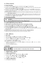
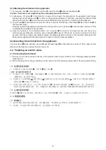
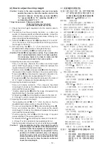
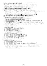
(2) How to adjust the crimp height
(Caution) In prior to the press operation, be sure to manually
operate the press to check the location at which the
terminal is crimped. At this time, set wire disk
1
to
“A,” spacer disk
2
to “W,” adjusting dial
3
to “1,”
and adjusting dial GT 4 to “1.”
Things to be prepared •Crimping condition list
• Crimp height measuring instrument
(Point blade micrometer and the like)
1) Check the crimp height requirement for the electric cable to
be crimped.
2) The terminal has three crimping positions, i.e., cable core
section
C
, shield section
D
and sheath section
E
. Adjust the
related crimp heights to the required values following the
steps of procedure described below.
3) Set wire disk
1
and spacer disk
2
respectively to “A” and “W.”
(Turn the disks so that the predetermined setting positions
are brought to the front.)
4) Set adjusting dial
3
to “1.” (Turn the dial so that the
predetermined setting position is brought to the top.)
You can turn adjusting dial
3
by drawing toward you.
(Caution) The dial
3
incorporates a spring. If you release the
dial, it will automatically return to its home position.
It is necessary, however, to check to make sure that
it has properly returned to the home position.
1
Adjusting the cable core crimp height
* Carry out crimping. Measure the cable core crimp height
with a DF1B height gauge to find a difference between the
required value and the measured value.
* Position of wire disk
1
and spacer disk
2
within the range of
the required crimp heights referring to the values given below.
* For wire disk
1
, the crimp height is reduced in the order of A,
B, C and D in increments of approximately 0.12 mm.
* For spacer disk
2
, the crimp height is reduced in the order of
W, X, Y and Z in increments of approximately 0.03 mm.
2
Adjusting the shield crimp height
* Carry out crimping operation. Then, measure the shield
crimp height to check up the difference between the required
value and the measured value.
* Position adjusting dial
3
within the range of required crimp
heights referring to the values given below.
* For adjusting dial
3
, the crimp height is reduced in the order of 1,
2, 3 through 7 and 8 in increments of approximately 0.05 mm.
3
Adjusting the sheath crimp height
* Set adjusting dial GT
4
to “1.” (Turn the dial so that the
predetermined setting position is brought to the top.)
* You can turn adjusting dial GT
4
by removing fixing screw
!5
.
* Carry out crimping operation. Then, measure the sheath
crimp height to check up the difference between the required
value and the measured value.
* Position adjusting dial GT
4
within the range of required
values referring to the values given below.
* For adjusting dial GT
4
, the crimp height is reduced in the order of 1,
2, 3 through 7 and 8 in increments of approximately 0.05 mm.
* After the completion of adjustment, be sure to tighten fixing screw
!5
.
(Caution) 1. At every adjustment of the crimp height, be sure to
detach fixing screw
!5
before the adjustment and
re-attach it after the completion of the adjustment.
2. Once you have completed the adjustment of the
positions of all disks and dials, carry out crimping
operation again to be sure that the respective
crimp heights satisfy the requirements. At this
moment, be sure to crimp the electric cable and
check the crimp height.

