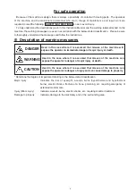
background image

vi

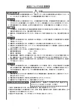
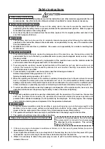
Safety instructions

Basic safety instructions


1.  Be sure to read this Instruction Manual and all the instructions and other materials supplied with the unit 

as accessories.  Save this Instruction Manual and make it available for review whenever necessary.

Safety device and warning labels


1.  To avoid possible accidents due to lack of the safety device, be sure to operate the machine after 

ascertaining that the safety device is properly installed at the predetermined position.  Refer to page viii 

for detailed description of the safety device.


2.  Once the safety device is detached from the machine, replace it to its original position and check to be 

sure that it properly functions.

Application


1.  This machine shall only be used for its originally intended purpose while following the instructions 

specified in this Instruction Manual. Hirose assumes no responsibility for any use of the machine other 

than the intended use.


2.  Modifications to this machine is prohibited.  We assume no responsibility for accidents resulting from 

modifications.

Operating environment


1.  To avoid possible accidents caused by maloperation of the machine, use the machine under the 

environment that is not affected by a substantial noise source (electromagnetic wave) such as a high-

frequency welder.


2.  To avoid possible accidents caused by maloperation of the machine, never use the machine under the 

environment where the voltage exceeds ±10% of the rated voltage.


3.  To avoid possible accidents caused by maloperation of the machine, put any device such as an air 

cylinder that operates by the pneumatic pressure into service after checking to ascertain that the 

specified pressure is provided.


4.  To ensure safety in operation, use the machine under the following environment.


  Ambient temperature during operation: 5 ˚C to 35 ˚C


  Relative humidity during operation: 35 % to 85 %


5.  When the operating environment of the machine is suddenly changed such as in the case where it is moved 

from a cold place to a warm place, dew condensation can occur.  To avoid possible accidents caused by 

breakage or maloperation of the electrical parts due to dew condensation, be sure to wait for a sufficient period 

of time until there is no possibility of presence of water drops inside the machine before turning the power on.


6.  To avoid possible accidents caused by breakage or maloperation of the electrical parts, be sure to stop 

operation and disconnect the power plug for safety in case of thunder and lightning.

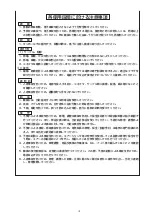
Training


1.  To prevent possible accidents caused by unfamiliarity with the operation of the machine, the machine 

shall only be allowed to be used by the operators who have been trained for proper operation and 

provided with sufficient knowledge of safe operation by the employee.  For this purpose, the employer 

shall establish a training plan and implement it for the operators beforehand.

Working wear


1.  To protect against possible accidents resulting in personal injury by your cloths being caught in the 

machine, be sure wear a work uniform and securely fasten buttons on the sleeve cuffs and close the 

zipper on the top center plait of the uniform, if any. Avoid wearing loosely fitted clothing.


2.  The operator should fasten hair securely to avoid his/her hair from being caught in the machine.


3.  The operator should wear close toe, rubber sole shoes.

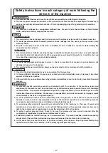
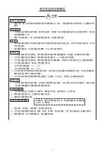
Cases which require the power to be turned off

CAUTION

Turn-off of the power means the state where 

the power switch is turned off and power plug 

is detached from the receptacle.  This will also 

apply to the following.


1.  If there is any sign of abnormal conditions or failure, or in the case of power failure, be sure to 

immediately turn the power off.


2.  To avoid possible accidents due to an abrupt start of the machine, be sure to turn the power off in prior 

to inspection, repair or cleaning of the machine or before leaving from the machine.


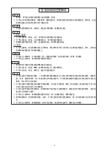
3.  Where it is necessary to detach the power plug, be sure to pull it out while holding, by hand, the plug 

instead of the cord.

Summary of Contents for CM-105

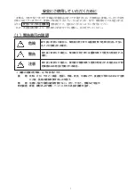
Page 1: ...すぐに読めるように この取扱説明書を保管してください 注意 CAUTION Be sure to read this Instruction Manual carefully before using it to secure safety in operation In addition save this Instruction Manual so that it is available whenever necessary for review CM 105 为了安全地使用机器 使用之前请一定阅读本使用说明书 另外 请注意妥善保管本使用说明书 以便可以随时查阅 注意 广濑电机株式会社 エアーシリンダータイプ Air cylinder type 气缸式 取扱説明書 INSTRUCTION MANUAL 使用说明书 ...

Page 2: ......

Page 3: ...ださい なお 本取扱説明書および 警告表示の内容を十分に理解し 指示を守ってください I 警告表示の説明 損害の程度の分類は 以下を参考とする 重 傷 失明 けが やけど 高温 低温 感電 骨折 中毒などで 後遺症が残るものおよび治療 に入院 長期の通院を要するものを言う 傷 害 治療に入院や長期の通院を要さない けが やけど 感電などを指す 物的損害 家屋 家財および家畜 ペットにかかわる拡大損害を指す 取り扱いを誤った場合に 使用者が傷害を負う危険が想定される場合および物 的損害のみの発生が想定される場合 取り扱いを誤った場合に 使用者が死亡または重傷を負う可能性が想定される 場合 注意 警告 危険 取り扱いを誤った場合に 使用者が死亡または重傷を負う危険が切迫して生じ ることが想定される場合 ...

Page 4: ...を使用している装置は 指定の圧力を確認 してから使用してください 4 安全にお使いいただくために 次の環境下でお使いください 動作時雰囲気温度 5 35 動作時 相対湿度 35 85 5 電装部品損壊 誤動作による事故を防ぐため 寒いところから急に暖かいところなど環境が変わった 時 結露が生じることがありますので 十分に水滴の心配がなくなってから電源を入れてください 6 電装部品損壊 誤動作による事故を防ぐため 雷が発生している時は安全のため作業をやめ 電源プ ラグを抜いてください 教育訓練 1 不慣れによる事故を防ぐため この機械の操作についての教育 並びに 安全に作業を行うため雇用 者による教育を受け 適性な知識と操作技能を有するオペレータのみが この機械をご使用ください そのため雇用者は 事前にオペレータの教育訓練の計画を立案し 実施することが必要です 作業時の服装 1 衣類の巻き込...

Page 5: ...電源を投入する前に コネクタ ケーブル類に損傷 脱落 緩み等がないこと を確認してください 2 人身事故を防ぐため 運動部分に手を入れないでください 給 油 1 機械には 当社指定オイルまたは同等品を使用してください 2 炎症 カブレを防ぐため 目や身体に油が付着した時は直ちに洗浄してください 3 下痢 嘔吐を防ぐため 誤って飲み込んだ場合 直ちに医師の診断を受けてください 保 守 1 不慣れによる事故を防ぐため 修理 調整は機械を熟知した保全技術者が本取扱説明書の指示範囲で 行ってください また 部品交換の際は 当社純正部品を使ってください 不適切な修理 調整およ び非純正部品による事故に対しては 当社は責任を負いません 2 不慣れによる事故 感電事故を防ぐため 電気関係の修理 保全 配線含む は電気の専門知識のあ る人 または当社の技術者に依頼してください 3 不意の起動による事故を防...

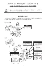
Page 6: ...いる機械および安全装置はあくまで 日本国内仕様として製造された機種およびそれに 装着 同梱された安全装置であり 仕向地 仕様により異なる場合もあります フートスイッチカバー 足への危険を防止するカ バーです ご使用上の注意 圧着機操作時の 最 低限の注意が記載さ れています 警告ラベル 内部に電装部があり 感 電の危険あり 警告ラベル 触れると火傷をする事が ある フライホイール等による 手 頭髪等の巻き込みを 防止するカバーです フライホイールカバー 警告ラベル カバー内には回転物があ り 巻き込み 挟み込み の危険あり 安全カバー 指とプレス部の接触を 防止するカバーです 指を切断する危険あ り 安全カバー内には 絶対指を入れない事 警告ラベル アプリケーター側 本体側 ...

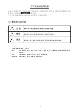
Page 7: ...impairment referring to the below stated classification Major injury Indicates the loss of eyesight wounds burns hyperthermal and hypothermal burns electric shocks fracture of a bone poisoning etc requiring emergency of extended medical care Injury Minor injury Indicates wounds burns electric shocks etc requiring medical treatment Damage to property Indicates damage to the machinery and or the sur...

Page 8: ...ine is suddenly changed such as in the case where it is moved from a cold place to a warm place dew condensation can occur To avoid possible accidents caused by breakage or maloperation of the electrical parts due to dew condensation be sure to wait for a sufficient period of time until there is no possibility of presence of water drops inside the machine before turning the power on 6 To avoid pos...

Page 9: ... get in your eye or contact your skin immediately wash to remove it to protect against irritations and rashes 3 In the event that you should swallow oil by mistake immediately consult a doctor to prevent diarrhea and emesis Maintenance 1 To prevent possible accidents caused by unfamiliarity with the operation of the machine repair and adjustment of the machine shall be conducted only by maintenanc...

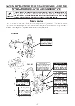
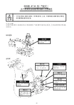
Page 10: ...supplied with the machine The configurations may differ with destinations and specifications Main unit Applicator CAUTION Warning label Electrical components are installed inside Danger of electric shocks is present Safety instruction in use The minimum safety i n s t r u c t i o n s t o b e followed when operating the crimping machine are indicated The cover protects feet against hazards Danger o...

Page 11: ...和 维修人员一定仔细阅读 安全注意事项 避免受伤 另外 请充分理解本使用说明书和警告表示的内容 并遵守指示操作 损害程度请参考以下的分类 重伤 指发生失明 负伤 烫伤 高温 低温 触电 骨折 中毒等后遗症和需要住院长期治疗 的伤害 伤害 不需要住院 长期治疗的负伤 烫伤 触电等伤害 财物损害 指有关房屋 财产以及家畜 宠物的损害 操作错误 有可能发生预想的使用者负伤的危险和物品损害的可能 操作错误 有发生预想的使用者死亡或负重伤的可能 注意 警告 危险 操作错误 有发生预想的使用者死亡或负重伤的危险 I 警告表示的说明 ...

Page 12: ...故 请不要在超过额定电压 10 的地方使用机器 3 为了防止因误动作发生事故 使用气缸等压缩空气的装置时 请确认了符合指定压力之后再使用机器 4 为了安全地使用机器 请在以下的环境下使用 动作时的环境温度 5 35 动作时的相对湿度 35 85 5 为了防止电气零件损坏和误动作发生事故 从寒冷的地方急速移动到温暖的地方时 会发生结露现象 请待水滴完全干燥之后再打开电源 6 为了防止电气零件损坏和误动作发生事故 打雷时 为了安全 请停止工作拔掉电源插头 教育训练 1 为了防止因不熟练而发生事故 应就本机器的操作进行教育 并对雇用人员进行安全教育 只能让具有 一定知识和掌握操作功能的操作者使用本机器 工作时的服装 1 为了防止衣服卷入机器发生人身事故 请穿着工作服 并扣好钮扣 拉好拉链 2 请把头发放进帽子里 以便避免头发卷入机器 3 请穿可以系带固定的鞋 必须关掉电源的事项 1 发生异常 故...

Page 13: ...插座上 运转前 1 为了防止人身事故 打开电源前 请一定确认连接器 电缆没有损伤 脱落 松驰等 2 为了防止人身事故 请不要把手伸到转动部分 加 油 1 请使用本公司指定的机油或同等品给机器加油 2 为了防止发炎 脓肿 眼睛 身体粘附油之后 请立即清洗 3 为了防止泻肚 呕吐 误饮后 请立即去医院治疗 维 修 1 为了防止因不熟练发生事故 一定请熟悉机器的维修技术人员在本使用说明书规定范围内修理 调整机 器 另外 更换零件时 请一定使用本公司的纯正零件 对于错误的修理和调整以及非纯正零件发生的 事故 本公司不负任何责任 2 为了防止因不熟练而发生的事故和触电事故 有关电气的修理 维护 包括配线 请让具有电气专门知 识的人或本公司的技术人员来修理 3 为了防止突然的起动造成事故 修理或维护气缸等空气压缩装置时 请拔掉空气供给源的软管 排出残 留空气之后再进行操作 4 为了防止人身事故 修理调...

Page 14: ... 也不要把物品放到机器上面 注意 关于安全装置 这里说明的机器和安全装置是作为日本国内规格生产的机器和同包装的安全装置 出口地区和规格不同机器也 可能不同 这是防止手 头发等卷入 飞轮的护罩 飞轮护罩 警告标签 护罩内有转动零件 有发 生卷入 夹入的危险 这是防止手指和冲压部 接触的护罩 有切断手指的危险 请 绝对不要把手指放入安 全护罩 警告标签 供料器侧 安全护罩 主机侧 警告标签 触摸后有发生烫伤的危 险 警告标签 内部有电气零件 有触 电的危险 使用时的注意事项 操作压接机器时的最低 限度注意事项 脚踏开关护罩 这是防止伤害到脚的危 险的护罩 ...

Page 15: ...端子の取り付け 7 4 アプリケーターからの端子の取り外し 7 4 2 電線の準備 7 1 端末加工 7 4 3 圧着作業準備 9 1 圧着作業方法 9 2 クリンプハイトの調整方法 11 5 圧着品質 13 5 1 圧着条件 13 5 2 圧着品質基準 13 6 圧着作業基準 15 7 メンテナンス 15 1 給油 15 1 1 ラム摺動部 15 1 2 端子送り機構摺動部 15 2 日常のお手入れについて 15 3 消耗部品の交換 17 3 1 クリンパの交換 17 3 2 アンビルの交換 17 4 消耗部品一覧表 17 8 トラブル処置 19 1 アプリケーター機能上トラブル 19 2 圧着品質上トラブル 21 3 フィードフィンガーの位置調整 23 4 スクラップガードの取付位置調整 23 5 端子位置の調整方法 25 9 付録 27 1 主要部品名称 27 2 電気ボックス配線図...

Page 16: ...g preparation for crimping operation 10 1 How to conduct crimping operation 10 2 How to adjust the crimp height 12 5 Crimping quality 14 5 1 Crimping conditions 14 5 2 Crimping quality standards 14 6 Procedure for crimping 16 7 Maintenance 16 1 Lubrication 16 1 1 Sliding section of the ram 16 1 2 Sliding section of the terminal feed mechanism 16 2 Routine maintenance and inspection 16 3 Replacing ...

Page 17: ...3 向供料器安装端子 8 4 从供料器拆卸端子 8 4 2 电线的准备 8 1 终端加工 8 4 3 压接作业准备 10 1 压接作业方法 10 2 夹紧高度的调整方法 12 5 压接质量 14 5 1 压接条件 14 5 2 压接质量标准 14 6 压接作业顺序 16 7 维修 16 1 加油 16 1 1 压头活动部 16 1 2 端子传送机构活动部 16 2 关于日常保养 16 3 消耗零件的更换 18 3 1 夹紧器的更换 18 3 2 砧台的更换 18 4 消耗零件 18 8 故障处理 20 1 供料器功能的故障 20 2 压接质量的故障 22 3 供料指的位置调整 24 4 废屑防护器安装位置的调整 24 5 端子位置的调整方法 26 9 附录 29 1 主要零件名称 29 2 电气箱配线图 32 3 压缩空气电路图 34 ...

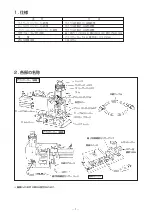
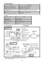
Page 18: ... ラム下死点時 縦 高さ 170 mm X 横 230 mm X 奥行き 80 mm 重 量 アプリケーター 5 kg 電気ボックス 2 9kg 適合圧着機本体 CM 105 型 2 各部の名称 中継ケーブル シャンク ワイヤーディスク スペーサーディスク ラム アジャストダイヤル 安全カバー スクラップガード ベースプレート ターミナルレール カムレバー 機種により形状の異なる場合があります アジャストダイヤル GT ケーブルストッパー 中継エアホース 端子有無確認センサーコード 電源スイッチ 端子有無確認センサーアンプ レギュレーター エアー圧 調節つまみ アプリケーター 表側 アプリケーター 裏側 電気ボックス ...

Page 19: ...k 衬垫圆盘 Safety cover 安全护罩 Scrap guard 废屑防护器 Base plate 底板 Terminal rail 台轨 Cam lever 凸轮杆 2 Configuration 1 规格 2 各部的名称 Applicator front side 供料器 正面 Adjusting dial 调节拨盘 Adjusting dial GT 调节拨盘 GT Cable stopper 电缆止动器 Junction cable 连接电缆 Applicator rear side 供料器 背面 Junction air hose 连接空气软管 Terminal presence absence checking sensor cord 确认有无端子传感器电线 Terminal presence absence checking sensor amplifier 确认有无...

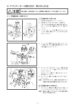
Page 20: ...方向に倒しつづけ シャ ンク 5 を持ち上げ 完全に抜かないこと 本体 の溝部 6 に合わせてください 5 アプリケーターをボルスタープレート 3 上面に乗 せ ストッパーブロック 7 に突き当たるまで滑り こませてください この時 シャンク 5 がラム 9 に取り付いている 事を確認してください 6 クランプレバー 8 を矢印 A 方向に回して締め付 けてください 注意 これでアプリケーターの取り付けは完了です こ の状態での空打ちは絶対に行わないでください 2 圧着機本体からの取り外し 1 クランプレバー 8 を矢印 B 方向に回して緩め ア プリケータを引くようにして取り外してください 注意 取り外しの際 アプリケーターに手や指を挟まれ ないようご注意ください 不意の起動による事故を防ぐため 圧着機本体の電源を切ってから作業を行ってください 2 1 3 7 5 6 4 9 5 A 7...

Page 21: ...t this time make sure that shank 5 is attaching on ram 9 6 Press clamp lever 8 in the direction of arrow A until it is secured Caution This completes the installation of the applicator Never carry out a false placement in this state 2 Detaching the applicator 1 Loosen clamp lever 8 by turning it in the direction of arrow B and pull the applicator until it comes off Caution When detaching be carefu...

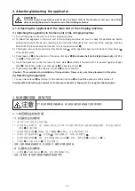
Page 22: ...る端子有無確認セ ンサーコード 9 を電源ボックスのセンサーアン プ 0 に差し込んでください 差し込み方は電気 ボックス添付のファイバーセンサ取扱説明書を参 照してください 6 電源コードのプラグ 1 を電源コンセントに接続し てください 5 6 9 0 7 8 1 1 3 4 2 7 0 4 圧着作業 注意 不意の起動による事故を防ぐため 圧着機本体の電源を切ってから作業を行ってください 1 圧着機本体へのリール端子の取り付け 1 ちょうねじ 1 を緩めフランジ 2 を外し リール 端子 3 をリールシャフト 4 に通してください 2 再びフランジ 2 を入れ軽く押え ちょうねじ 1 を締め 取り付けてください 3 1 4 2 A 6 5 3 リール端子 3 を矢印 A 方向に回しながら 紙テー プ 5 と共に 端子 6 を引き出してください 4 端子 6 は 圧着機本体左側を通りター...

Page 23: ...d air supply to the regulator since the feed lever can move 5 Insert terminal presence absence checking sensor cord 9 coming from the rear face of the applicator into sensor amplifier 0 Refer to the Instruction Manual for the fiber sensor supplied with the electrical box for how to insert the cord 6 Connect power cord plug 1 to the power receptacle 4 Crimping operation 为了防止突然的起动造成事故 请关掉压接机主机的电源之后再...

Page 24: ...程度まで挿入 してください そのときカットオフパンチ 3 を矢 印 D 方向に押しながら通すと引っかかりが無く端 子が通ります 3 ねじ 1 を矢印 E 方向に下げ フィードフィン ガー 4 の先端が端子キャリアのパイロット穴 5 に入っていることを確認してください リール端子を若干矢印 F 方向に引き カムレバー 8 を矢印 C 方向に回転させてください 4 端子を圧着位置に合わせたら 電気ボックスのス イッチ 6 を ON にし 端子有無確認センサーラ ンプ 7 の反応を確認してください 赤 緑のラ ンプが同時に点灯する状態が端子最適位置です なお センサーアンプの調整方法は電気ボックス 添付のファイバーセンサー取扱説明書を参照して ください 4 アプリケーターからの端子の取り外し カムレバー 8 を矢印 B 方向に回転させ フィード フィンガー 4を矢印C方向に上げてください 次に ...

Page 25: ...When the terminal is placed at the best position both the red and green indicator lamps simultaneously light up Refer to the Instruction Manual for the fiber sensor supplied with the electrical box for how to adjust the sensor amplifier 4 Detaching the terminal from the applicator Turn cam lever 8 in the direction of arrow B and lift feed finger 4 in the direction of arrow C Then draw out the term...

Page 26: ... AWG30 のように細い場合は電線被 膜の肩部 6 を端子の端面部 7 に突き当ててから 手前に少し引いて位置決めしてください 5 フートスイッチを踏んでください 圧着機ラム部が1回上下動作することにより ア プリケーターラムが上下動作し 圧着作業が行わ れます 5 1 2 3 7 6 注意 4 3 圧着作業準備 不意の起動による事故を防ぐため 圧着機本体の電源を切ってから作業を行ってください あらかじめ圧着条件 クリンプハイト と圧着品 質基準 圧着形状 をご確認ください 当社より 発行の圧着条件表 圧着品質基準書を参照してく ださい 1 圧着作業方法 1 ワイヤーディスク 1 スペーサーディスク 2 ア ジャストダイヤル 3 アジャストダイヤル GT4 の位置を左図と同じ位置 A W 1 1 にセットし てください 設定する位置 Setting Positions 设定的位置 1 2...

Page 27: ...stripped end of the electric cable against wire stopper 5 at a position that is almost just above the terminal Caution If crimping is carried out with the electric cable separated from wire stopper 5 or excessively pressed against it crimping quality deficiencies can result The top end of electric cable is as thin as AWG30 firstly press shoulder portion 6 of the electric cable sheath against end f...

Page 28: ... 値との差を確認してください アジャストダイヤル GT4 の位置を 下記の数 値を参考にして規格値内に合わせてください アジャストダイヤル GT4 は 1 2 3 7 8 の順番に 1 目盛りごとに白字のダイヤルは約 0 1mm 青字のダイヤルは約 0 05mm クリン プハイトが低くなります 調整後は必ず固定ねじ 5 を締め付けてください 1 2 3 設定する位置 Setting Positions 设定的位置 ハイトゲージについて 当社 GT 端子の芯線クリンプハイト測 定には下記専用ハイトゲージをご使用 ください ゲージ先端部が専用形状 になっています 品名 DF1B ハイトゲージ 販売元 横山機工株式会社 143 東京都大田区大森本町 2 1 19 TEL 03 3765 6621 FAX 03 3765 6603 当社ではこのハイトゲージの直接販売は 行っておりません このハイト...

Page 29: ...t will automatically return to its home position It is necessary however to check to make sure that it has properly returned to the home position 1 Adjusting the cable core crimp height Carry out crimping Measure the cable core crimp height with a DF1B height gauge to find a difference between the required value and the measured value Position of wire disk 1 and spacer disk 2 within the range of t...

Page 30: ...確認してください 断面 Y Y 断面 Z Z 撚線の場合 項 目 測 定 箇 所 及び 寸 法 ストリップ長さ L1 L2 L3 圧着位置 A B C D ベルマウス E F ベントダウン G H ベントアップ I J ローリング K M ツイスト N O カットオフタブ P Q 圧着バリ高さ R X 部拡大図 Y Y Z Z A B A X X 断面 X X A C B C 断面 Y Y 断面 Z Z 断面 X X 単線の場合 項目 箇所 芯線クリンプハイト A シールドクリンプハイト B 被覆クリンプハイト C B C D O X Y Y I G N Z Z Q H J 断面 Y Y 断面 Z Z L3 L2 L1 R K E F P M ...

Page 31: ...D 钟罩 E F 出口下降 G H 出口上升 I J 压接 K M 捻线 N O 切开凸头 P Q 压接毛刺高度 R Cross section YY 断面 YY Cross section ZZ 断面 ZZ In case of stranded wire 捻线时 Y Y Z Z B A X X Cross section XX 断面 XX A C In case of solid wire 单线时 Item Spot Cable core wire crimp height A Shield crimp height B Sheath crimp height C B C D O X Y Y I G N Z Z Q H J L3 L2 L1 R K E F P M 项目 部位 芯线夹紧高度 A 屏蔽夹紧高度 B 被覆加紧高度 C Cross section YY 断面 YY Cross...

Page 32: ... 1 2 端子送り機構摺動部 1 週に 1 度フィードロッド 4 LM ガイド 5 に 2 3 滴給油してください 推奨オイル規格 ISO VG32 68 注意 1 上記は ISO 規格の粘度 32 68 を表して います 例として 日石 タービンオイル 32 昭和シェル テラスオイル 32 等があります 2 過剰給油は避けてください 2 日常のお手入れについて 1 各スライド部にキャリアチップ ゴミなどがない事を確認してください 6 部にはメッキカスが付着しやすいため 定期的 一日の作業終了時 またはリール交換時等 にアルコー ルを塗布したウエス等で拭いてください 2 使用しないときは できるだけホコリを避け湿気のない場所に保管してください 3 使用するときは 必ず消耗部品が正規なものかを確認の上ご使用ください 2 1 3 6 4 5 6 圧着作業基準 1 アプリケーターの各ディスクを ...

Page 33: ...nd dust gather in each sliding section The residue of plating is apt to adhere to the section 6 Periodically at the end of the daily work at the time of replacement of the reel etc wipe there with waste soaked with alcohol Or the like 2 It is recommended to store the machine when not in use in a clean and dry place to avoid dust and dirt 3 To put the machine into service be sure to check in prior ...

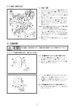
Page 34: ...ルの交換 1 取り外し方は アンビル取付ボルト E 2 本 を 外し アンビルの各部品を取り外してください 2 取り付け方は アンビルの各部品のセット順序を まちがわないようにセットし アンビル取付ボル ト E 2 本 で固定してください なお 固定の 際はアンビルがベースプレート F に密着している 事を確認してください 注意 1 アンビルセットの際には アンビルホルダー I の内部 およびアンビルにゴミや汚れの無いよ う 十分に清掃を行ってください 2 各アンビルは 表示側が作業者側に向くように セットしてください 3 カットオフパンチ 7 はスプリング G により上 に持ち上げる力が働きますので 注意してくだ さい また 端子受け台 H の入れ忘れに注意 してください 4 消耗部品一覧表 1 8 の部品には 刻印が表示されております ご注文の際は アプリケーターに添付の スペア部品取...

Page 35: ...l carefully clean the inside of the anvil holder I and the anvil so that there is no dust or stain there 2 Set each anvil that the side on which indications are given faces toward the operator 3 Extra caution is needed at the time of attaching the anvil since cut off punch 7 applies a lifting force by means of its spring G In addition be sure to place terminal support H without fail 3 消耗零件的更换 3 1 ...

Page 36: ...量が適正値 0 4 0 6MPa になっていない 3 バルブへのエアー供給調整が悪い 1 スクラップガードの取り付け位置 が悪く リール端子キャリアと衝 突している 2 カットオフパンチにキズ 打刻が 付いているため 上下の動きが悪 い 処 置 1 フィードフィンガーの取り付け 位置を再度調整してください 2 フィードフィンガーを新しい物 と交換してください 弊社までご相談ください 3 カムフォロアーを新しい物と交 換してください 弊社までご相談ください 1 端子位置にセットしてください 2 レギュレータの調整をし エアー 供給量を 0 4 0 6MPa に調 整してください 3 バルブ部のスピードコントロー ルを調整してください つまみ 1 を緩め つまみ 2 を A 方 向にすると 送出し 戻り のスピー ドが速くなります つまみ 1 を緩め つまみ 2 を B 方 向にすると 送出し...

Page 37: ...ve Loosen knob 1 and turn knob 2 in direction A to increase the feeding and returning speeds Loosen knob 1 and turn knob 2 in direction B to decrease the feeding and returning speeds 1 Re adjust the attaching position of the scrap guard 2 Replace the cut off punch with a new one Related page 故障 1 端子不能顺畅 传送 原因 处理 1 供料指的安装位置偏移 没有对准卷盘端子 传送的操作杆孔的中心 2 供料指的前端磨损 3 凸轮磨损 1 端子没有安放在压接位置 砧台的正上方 2 空气供给压力不是规定值 ...

Page 38: ...新しい物に交換してく ださい なお その際 アンビル も同様に摩耗している事が予測さ れますので交換をお勧め致します 1 再度調整が必要です 1 クリンパを新しい物と交換してく ださい 1 アンビルを新しい物と交換してく ださい 原 因 1 アンビルの取り付けが悪く ベー スプレートに密着して取り付けら れていない 2 クリンパの摩耗 破損 により 端子が食い付き現象を発生させ 圧着完了後 ケーブルストッパー で払い落とす際 端子が変形する ベントダウン 1 端子位置が アンビルのセンター とずれている 1 クリンパが極端に摩耗 破損 キズ している 1 アンビルが極端に摩耗 破損 キズ している 関連ページ P17 P17 P23 P17 P17 ご使用にあたってのご相談もしくはご不明な点は 当社生産技術部までご連絡ください ...

Page 39: ...mproperly attached and fail to be closely fitted against the base plate 2 Crimper has worn out broken to cause the terminal to bite After the completion of crimping the terminal deforms when wiping off the terminal with the wire stopper Bent down 1 Terminal is attached to a position that is not aligned with the center of the anvil 1 Crimper has extraordinarily worn out breakage and scratches 1 Anv...

Page 40: ...レンチでスクラップガード取付ねじ 3 を締め 付けてください B 方向 2 キャリアのパイロットホールの中心にフィード フィンガー 2 を合わせます 3 六角レンチでフィードフィンガー取付ねじ 1 を締 め付けます B 方向 注意 ねじを締め付けた後 再度フィードフィンガー の位置を確認してください 5 端子位置の調整方法 9 ローリング及びツイストの形状不良がありましたら端子位置の調整を行ってください 1 エアー源を電気ボックスのレギュレーターから外してください 2 端子をセットした状態でストッパーボルトホルダー固定ボルト 8 を緩めストッパーボルトホルダー 9 を取 り外してください 3 ストッパーボルト固定ナット 0 を緩めてください 4 端子 1 がアンビル 2 の左方にある場合はストッパーボルトを矢印 A 方向に回し 右方にある場合は矢印 B 方 向に回します 端子がアンビルの真...

Page 41: ...th carrier 4 coming out from the cut off punch Adjust the longitudinal position so that crimper 6 does not come in contact with scrap guard 5 3 Tighten scrap guard mounting screw 3 with a hexagonal wrench key direction B 5 How to adjust the position of the terminal If the rolling or twist is defective in shape adjust the position of the terminal 1 Detach the air supply from the regulator of the el...

Page 42: ... 1 39 ガイドプレート 1 40 プッシュロッド 1 41 プッシュロッドスプリング 1 42 プッシュロッドガイド 1 43 シリンダブラケット 1 44 シリンダヘッドシャンク 1 45 固定ナット 1 46 ストッパーボルト B 1 47 シリンダー保持プレート 1 48 エアーシリンダー 1 49 ハーフユニオン 1 50 バルブワッシャー 1 51 バルブナット 1 52 バルブ 1 53 ホース 3 54 スピードコントローラー 2 55 ホースエルボ 2 56 LM レール 1 57 LM ガイド 1 58 フィードレバー 1 59 フィードフィンガーピン 1 60 ストッパーボルトホルダー 1 61 ストッパーボルト A 1 62 安全カバーボルト 2 63 安全カバースペーサー 2 64 安全カバー座金 2 65 安全カバー蝶ねじ 2 66 安全カバー 1 67 ラム...

Page 43: ...40 Push rod 1 41 Push rod spring 1 42 Push rod guide 1 43 Cylinder bracket 1 44 Cylinder head shank 1 45 Fixing nut 1 46 Stopper bolt B 1 47 Cylinder retaining plate 1 48 Air cylinder 1 49 Half union 1 50 Valve washer 1 51 Valve nut 1 52 Valve 1 53 Hose 3 54 Speed controller 2 55 Hose elbow 2 56 LM rail 1 57 LM guide 1 58 Feed lever 1 59 Feed finger pin 1 60 Stopper bolt holder 1 61 Stopper bolt A...

Page 44: ...料指支架 35 供料指 36 供料指弹簧 37 辊销 38 供料辊 39 导板 40 推杆 41 推杆弹簧 42 推杆导向器 43 气缸架 44 气缸头轴 45 固定螺母 46 止动器螺栓 B 47 气缸保持板 48 气缸 49 半接头 50 阀门垫 51 阀门螺母 52 阀门 53 软管 54 速度控制器 55 软管接头 56 LM 轨 57 LM 导向器 58 供料杆 59 供料指销 60 指动器螺栓支架 61 制动器螺栓 A 62 安全护罩螺栓 63 安全护罩垫 64 安全护罩垫片 65 安全护罩蝶形螺丝 66 安全护罩 67 压头 68 压头销 69 轴 70 线圆盘 71 衬垫圆盘 72 圆盘珠 73 圆盘弹簧 74 调整拨盘 75 供料凸轮 76 肩螺旋 77 肩弹簧 78 线夹紧器 79 屏蔽夹紧器 80 绝缘夹紧器 81 绝缘衬垫 82 螺线管主体 83 调整拨盘 GT 8...

Page 45: ... 28 アプリケーター AP105 型 エアーシリンダータイプ Applicator Model AP105 Air cylinder type 供料器 AP105 型 气缸型 ...

Page 46: ... r トランス トヨズミ HT 2402 DB 1 整流器 C コンデンサ 50V 470 μ F G 3 端子安定器 DB 2 ダイオード S センサーアンプ サンクス FX4N A3R R リレー オムロン G2VN 237P NK ノイズキラー Foot switch フートスイッチ 電気ボックス R プレス CM 105 CN2 2 CN2 1 CN2 3 FOOT SW AC100V SW AC24V Tr DB1 DB2 C S R NK G IN OUT OUT 0V 24V ...

Page 47: ...Diode S Sensor amplifier SUNX FX4N A3R R Relay OMRON G2VN 237P NK Noise killer Foot switch Foot switch 符号 品名 型号 SW 开关 NKK M 2011E T r 变压器 丰澄 HT 2402 DB 1 整流器 C 电容器 50V 470 μ F G 3 端子镇流器 DB 2 二极管 S 传感器放大器 SUNX FX4N A3R R 继电器 Omron G2VN 237P NK 噪音抑制器 Foot switch 脚踏开关 Electrical box 电气箱 R Press CM 105 冲压器 CM 105 CN2 2 CN2 1 CN2 3 FOOT SW AC100V SW AC24V Tr DB1 DB2 C S R NK G IN OUT OUT 0V 24V ...

Page 48: ... 31 3 空気圧回路図 記号 名称 形式 1 シリンダー コガネイ社製 JDAS25X40 2 スピードコントローラー SMC 社製 AS1201F 5M 06 3 押しボタン型バルブ コガネイ社製 TAC 4P 4 レギュレーター コガネイ社製 R150 2 R1 R2 A B 1 2 3 4 ...

Page 49: ... by Koganei JDAS25X40 2 Speed controller Made by SMC AS1201F 5M 06 3 Pushbutton type value Made by Koganei TAC 4P 4 Regulator Made by Koganei R150 2 R1 R2 A B 1 2 3 4 符号 品名 型号 1 气缸 小金井公司制 JDAS25X40 2 速度控制器 SMC 公司制 AS1201F 5M 06 3 按扭型阀门 小金井公司制 TAC 4P 4 调节器 小金井公司制 R150 2 ...

Page 50: ... 33 MEMO ...

Page 51: ...our Marketing Department 4 It should be understood that notwithstanding the aforementioned item 3 we assume no liability to any claim for loss or failure to earn profit resulting from the use of the machine 5 We assume no responsibility for any damage resulting from your improper use of the machine including your failure to follow the instructions given in this Instruction Manual This includes rep...

Page 52: ...0711 4560021 Tele Fax 0711 4560729 Phone 0908 260616 Tele Fax 0908 563309 Phone 02 864 5075 Tele Fax 0345 491 9886 Phone 2803 5338 Tele Fax 2591 6560 Crownhill Business Centre 22 Vincent Avenue Crownhill Milton Keynes MK8 0AB Hirose Electric U S A Inc 2688 Westhills Court Simi Valley Calif 93065 6235 Hirose Electric GmbH Zeppelinstraze 42 73760 Ostfildern Kemnat Hirose Electric UK Ltd HIROSE KOREA...

Reviews: