background image

8

DF57 Series

Low Profile “Swing-Lock” Board to Wire Connector for Power

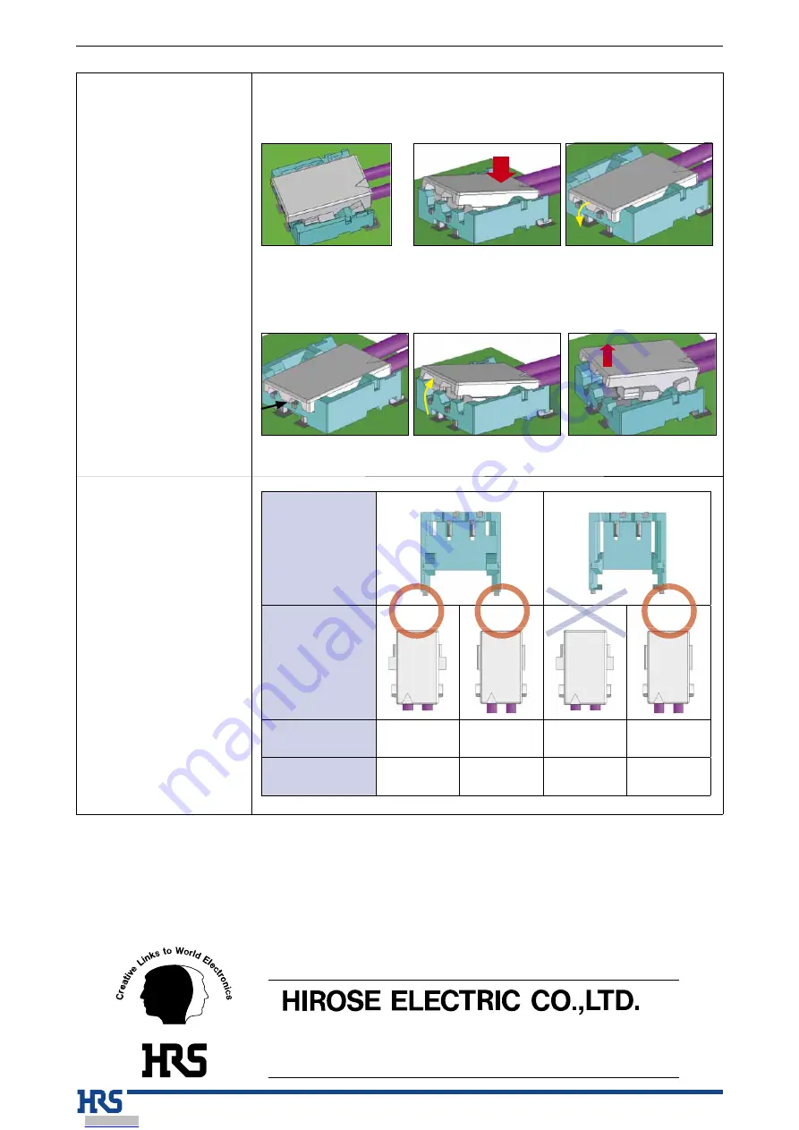
7.  Insertion and removal operation 

method

8. Mating compatibility

Mating

  Determine position, fitting 

the external form

 Insert the cable side

Un-mating

 Engage lever

  Pull up and release the 

simple lock

  The reinforced lock is also released 

and the un-mating is complete

 Push the contact portion side

Header

DF57H

DF57

Socket

DF57H

DF57

DF57H

DF57

Mating compatibility

Y

Y

N

Y

Additional guiding 

keys

Y

N

-

N

DF5

57H

57H

F5

F57

The characteristics and the specifications contained herein are for reference purpose.  Please refer to the latest customer drawings prior to use.

The contents of this catalog are current as of date of 06/2018. Contents are subject to change without notice for the purpose of improvements.

2-6-3,Nakagawa Chuoh,Tsuzuki-Ku,Yokohama-Shi 224-8540,JAPAN
TEL: +81-45-620-3526  Fax: +81-45-591-3726
http://www.hirose.com
http://www.hirose-connectors.com

®

Dec.1.2019 Copyright 2019 HIROSE ELECTRIC CO., LTD. All Rights Reserved.

Downloaded from

Arrow.com.

Downloaded from

Arrow.com.

Downloaded from

Arrow.com.

Downloaded from

Arrow.com.

Downloaded from

Arrow.com.

Downloaded from

Arrow.com.

Downloaded from

Arrow.com.

Downloaded from

Arrow.com.

Summary of Contents for DF57 Series

Page 1: ...roves mating operation and prevents possible connector breakage with incorrect mating 5 Solder wicking prevention The integral molding eliminates any gap between the terminals and case to prevent solder wicking 6 Case disengagement prevention Reinforcing hardware metal fittings are integrated in the molding which help prevent the case from disengaging with the terminals due to tough electric cable...

Page 2: ...cation 96 hours at 40 2ç and humidity of 90 to 95 7 Temperature cycle Contact resistance 20mø max Insulation resistance 500Mø min No damage cracks or parts dislocation 55 C 5 to 35 C 85 C 5 to 35 C Times 30 min 2 min to 3 min 30 min 2 min to 3 min 5 cycles 8 Durability Contact resistance 20mø max No damage cracks or parts dislocation 30 cycles 9 Resistance to soldering heat No deformation of compo...

Page 3: ...nk 28 to 34 AWG Insert guide key H Yes Number of contacts 2 3 4 5 6 Connector type S Crimp socket Contact pitch 1 2mm Termination section C Crimp socket Applicable wire size 2628 26 to 28 AWG 2830 28 to 30 AWG 3234 32 to 34 AWG Packaging SCF SCF Female crimp contact reel Plating type Blank Tin plating A Gold plating Number of contacts 2 Contact pitch 2 4mm Middle pin of 3 pos is removed and rated ...

Page 4: ...o of contacts A B C DF57H 2P 2 4V 666 0109 0 2 5 3 2 4 3 7 Unit mm Part No HRS No No of contacts A B C DF57H 2P 1 2V 666 0104 7 2 4 1 1 2 2 5 DF57H 3P 1 2V 666 0105 0 3 5 3 2 4 3 7 DF57H 4P 1 2V 666 0106 2 4 6 5 3 6 4 9 DF57H 5P 1 2V 666 0107 5 5 7 7 4 8 6 1 DF57H 6P 1 2V 666 0108 8 6 8 9 6 0 7 3 Note 1 Embossed tape reel packaging 5 000 pcs reel Note 2 The crossed shaded area is a no conductive t...

Page 5: ... 1 2C 666 0110 0 5 7 1 6 58 6 2 6 8 4 8 1 4 DF57AH 6S 1 2C 666 0111 2 6 8 3 7 78 7 4 8 0 6 0 1 4 Note 1 The quantity is delivered per pack 1 000 pcs Order by number of pack 2 125 0 3 CENTER OF VACUUM AREA CENTER OF VACUUM AREA DF57H 2P 1 2V DF57H 3P 1 2V DF57H 2P 2 4V DF57H 4P 1 2V DF57H 5P 1 2V DF57H 6P 1 2V 16 0 3 H 0 3 J 0 1 4 0 1 D E E G G G G E E D D D F F F F 0 1 0 Ø 1 5 0 1 0 Ø 1 5 2 0 1 4 ...

Page 6: ... 2C DF57 2628SCFA 41 666 0033 0 41 Reel 35 000 Gold plated DF57 2830SCF 666 0001 4 Reel 40 000 Tin plated 28 to 30 AWG DF57H S 1 2C DF57AH S 1 2C DF57 2830SCFA 666 0034 3 Reel 40 000 Gold plated DF57 3234SCF 666 0016 1 Reel 40 000 Tin plated 32 to 34 AWG DF57 3234SCFA Under planning Reel 40 000 Gold plated Note Embossed tape reel packaging 40 000 pcs reel Order by number of reels Part No Wire size...

Page 7: ...ert obliquely DO NOT mate un mate non terminated plugs with non mounted receptacles This may lead to damage or deformation of the contacts Removal of the holding electric cable may cause damage so please be careful DO NOT apply flux to the contact terminals when hand soldering the receptacle to the board Wicking of the flux into the electrical contact areas may lead to connection failures Slight d...

Page 8: ...cteristics and the specifications contained herein are for reference purpose Please refer to the latest customer drawings prior to use The contents of this catalog are current as of date of 06 2018 Contents are subject to change without notice for the purpose of improvements 2 6 3 Nakagawa Chuoh Tsuzuki Ku Yokohama Shi 224 8540 JAPAN TEL 81 45 620 3526 Fax 81 45 591 3726 http www hirose com http w...

Reviews: